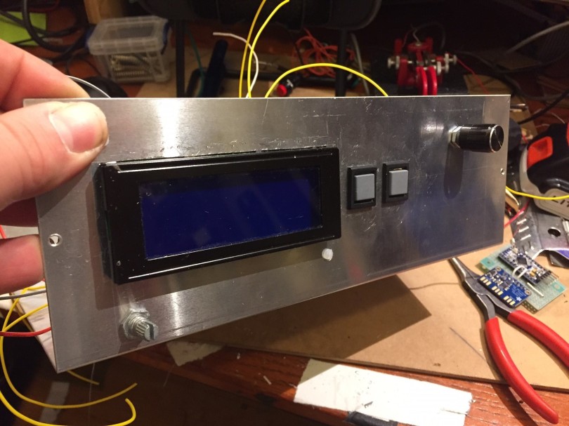
As I alluded to in my March bench report, I’ve been working on packaging up my old SI5351 VFO that sat on a breadboard for two years into a functional signal generator for the bench. That project is now essentially complete, though there are a couple of planned improvements in the works.

The heart of this project is a Silicon Labs Si5351 clock-generator IC, on a little interface module from Adafruit. With an I2C interface, it can output square-wave signals at roughly 6dBm anywhere from 8Khz to 160 MHz. This nifty little chip has been around for a few years, and has been used in many a homebrew radio rig, including the work of N6QW, N2CQR, M0XPD, and other. Jason NT7S was essentially in building some of the earlier Arduino-friendly libraries for controlling the Si5351. With such a wide frequency range and the confidence that comes from XTAL-derived, PLL frequency generation, this little chip has breathed life into rigs both new and old.
With the hardest part of building a SigGen (actually producing the darn frequency) neatly packed away in silicon, what remains for a builder is to wrap the thing in packaging to promote ease of use and flexibility. That’s where the fun of this project lay. The parts list ended up like so:
- 1 @ Si5351 Module
- 1 @ Arduino Pro Mini
- 1 @ 4×20 Backlit LCD display
- 1 @ Rotary Encoder
- 2 @ Momentary push-buttons
- 1 @ 10K Pot (contrast adjust)
- 1 @ On/Off SPST Switch
- 1 @ 5V Wall wart.
- 1 @ Aluminum box from Fry’s Electronics
The project box and the LCD display were the most expensive parts of this build by a wide margin, although both would be available for quite a bit less with a longer lead time from oversees.
The SigGen has 4 different software modes:
- VFO – The primary output frequency matched the displayed frequency. Frequency steps are 10kHz, 1kHz, 100Hz, and 10Hz.
- Test – Same as VFO, but steps are 10MHz, 5 MHz, 1 MHz, 500kHz, 100kHz, 10kHz, 1kHz, 100Hz, 10Hz, and 1Hz.
- Polyakov – Primary output frequency is half of the displayed frequency, for experimenting with half-frequency-driven mixers. Step size is the same as VFO mode.
- BFO – Adjusts the secondary output frequency, for using the SigGen to drive a Superhet directly. Steps are the same as in Test mode.
The SigGen’s three pushbuttons (one built into the rotary encoder and two next to the LCD screen) do essentially the same thing in each mode:
- Encoder: Changes the frequency step size, per the step options above.
- Mode: Changes through the software modes, per above.
- Band: Advances to the next highest Amateur band frequency, to aid with band-changes especially in VFO mode. For example, if the current frequency is 5.72MHz, pressing the Band button sets the frequency to 7.0Mhz, the bottom of the 40m band.
There are still a couple improvements I’d like to make, namely replacing the cheapo detent-based rotary encoder with a nice smooth continuous one, which can be had for about $10 on eBay – using a detent-based encoder as a VFO is a pain in the patoot. I’d also like to implement a sweep functionality to sweep through various filters, but that would require a bit more UI work as well.
This gadget has been complete on my bench for a month of so, and has already been useful in working on my variable-bandwidth superhet… but that’s a story for another post.
Hear you on the air!
73

[…] Note: This project ulimately got packed up into the Si5351 Signal Generator/VFO. […]
LikeLike
[…] This project ulimately got packaged up into the SI5351 Signal Generator/VFO. […]
LikeLike
I just finished a similar project. Maybe we should start a club.
https://wb8nbs.wordpress.com/2018/01/04/arduino-si5351-powered-signal-generator/
LikeLike
I see you had the same fight with rotary encoders I did. I have it tamed down pretty well see this post in the Adafruit forums https://forums.adafruit.com/viewtopic.php?f=57&t=117518 The last item there is what made it finally work.
LikeLike
[…] claim to do 0.1Hz-2.4GHz for only $70. A signal genetor is also really useful in my work – I built my own around an Si5351 and an Arduino, but you can buy a 0-25Mhz or 0-60Mhz arbitrary function generator […]
LikeLike