The 5W-to-50W QRP HF Amplifier project is rolling along nicely – I received the first PCB draft in the male this week and am 90% of the way through assembling it, with only heatsink-placement left to sort out.
I’ve made a couple of additions to the schematic since the original layout, including a relay-activated indicator (R27 and its LED) and an RF-output sensing LED (from C14 to its associated LED to ground) along the the lines of VK3YE’s recent project. There’s also a space on the PCB now for a low pass filter with the same footprint as Hans Summers’ LPFs over at QRP-Labs. Not that you’d necessarily want to reuse a QRP LPF for a 50W amp, you’d be in danger of putting too much voltage on the caps, but that would be a simple change.
Here’s the schematic as it exists now:

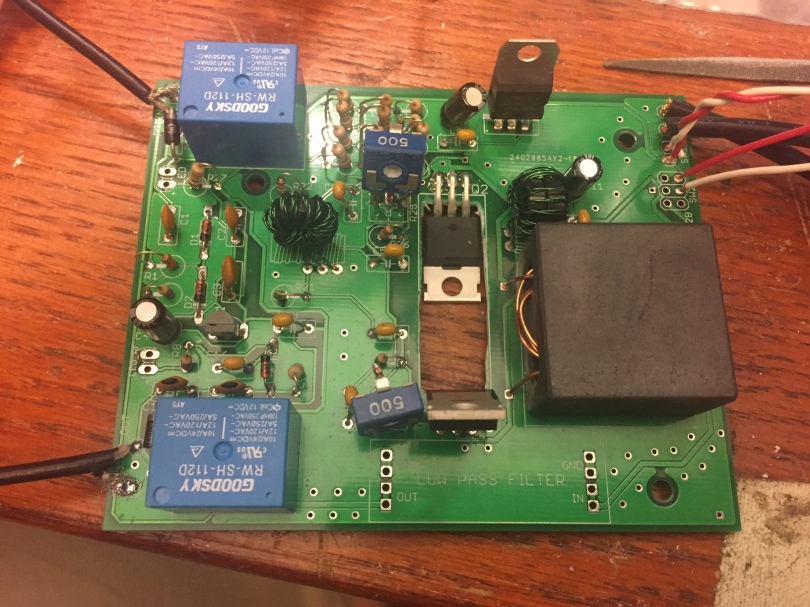
And here’s the current boards (layout, unpopulated, populated):


I’ve already got a little laundry list of things to modify for a second rev of this board, including, in no particular order:
- Swap the Diode placements the vertical to preserve board space
- Add footprints for alternate relay packages
- Add footprints for alternate trim-pot packages
- Re-think component designators for clarity
- Add bypass jumpers for the 3dB input pad and the LPF.
- For some reason, the none of the component values printed on the silkscreen, will need to sort that out
- I’m not sure if I screwed up how to designate a cutout or if JLCPCB doesn’t do them for its bare-bones PCB service, but I’d like not to do the next set with a drill press and a nibbler.
Hoping to put this on the air soon for some signal tests. Hear you there!
73
This post is cross-posted to my more general-purpose nerdery blog, jeff.glass/blog.

Hi Jeff, thanks very much for sharing this. I’ve built my own amplifier based on your design and it works pretty well. As mine is going into the enclosure with an 80m transceiver I’m building, I didn’t need the rf sensing section or the pi attenuator. But the amp itself was built to your design.
I’ve actually got a puzzling situation though: the amp works even without any bias to the mosfets! I’m not sure how this is possible but with +12-28V to the drains and a 1W signal applied to the gates then it works like a charm – even with no dc bias applied. I’ve swapped out the IRF510s but the results are the same. I’m a bit stuck with this one but at least it works!
Thanks again.
73,
Nick
M0NTV
LikeLike
Hi Jeff, thanks for sharing this project. I want to make this project to use handmade QRP. I would appreciate if you share the PCB gerber files. Thanks for all. TA2UCM, 73rd (coskunmuti@gmail.com)
LikeLike
Hi Coskun – I would gladly share the PCB’s, if only they worked better… this project never really got to a state where I think they’re of value to pass along. Sorry!
LikeLike