QST Forty-9er with DDS VfO

(Since this was originally posted, this transceiver has also gained a laser-cut faceplate.)

Long story short, I’ve got a new transceiver!

Back in March, QST magazine published an article about modding a cheap Forty-9er kit from eBay to incorporate a digital VFO. The original Forty-9er was a kit from the NorCal QRP club, a 40m transceiver designed to run on a 9V battery, hence the name. It, like many other kits, is based around an NE602 and an LM386. In the last couple years, cheap kits bearing the same name have been appearing on eBay, which bear only a scant resemblance to the original. The biggest difference is that where the original kit had a VXO attached to the NE602 mixer, the eBay kits are designed to be rock-bound to a single frequency. Perhaps this was the motivator for the QST article, to restore some frequency coverage to these fixed-frequency kits.

ebay 40-9er.jpg
The Forty-9er kits from eBay – not a huge number of parts, but not a tiny kit either.

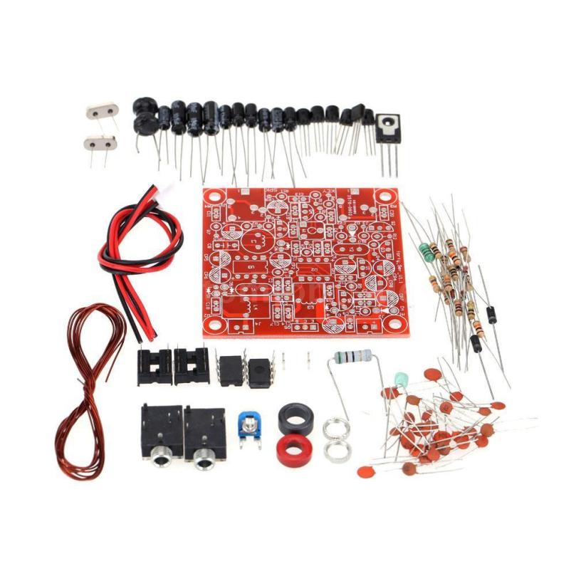
The process of using a digital VFO with an NE602 architecture is simple enough. Specifically, an AD9850 breakout board is used to provide the signal, and a small BJT amplifier increases the power output from the DDS chip. The oscillator power is adjusted to show about 300mV P-P in-situ. After the article was published, one of the authors, K2ZIA produced a limited run of kit boards, which include the amplifier and sockets for both the AD9850 board and an Arduino Nano to control the DDS over i2c.

K2ZIAboard
The K2ZIA kit board, with attached Arduino Nano and AD9850 board. Image credit: K2ZIA

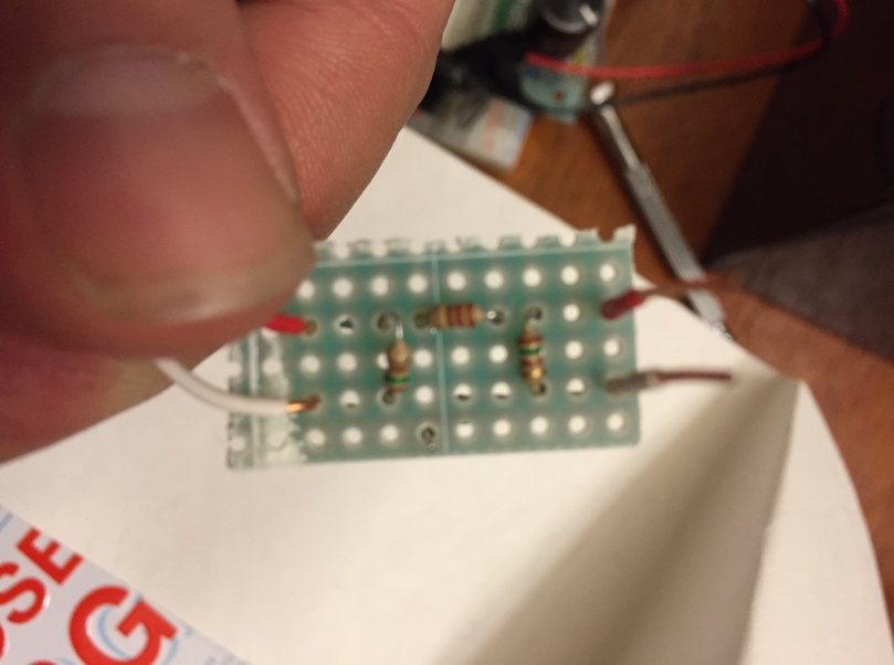
I purchased the breakout board, AD9850, Forty-9er kit, Arduino Nano, and a rotary encoder from a fellow ham, Justin AJ2Q, who had gathered the pieces but was focusing on other pursuits and wanted to pass the project on. Final assembly was pretty straightforward; there are a couple of mods that need to be made to the Forty-9er (specifically, replacing the oscillator crystal with an input for the VFO, and swapping the crystal input bandpass filter for a much-wider two-element bandpass filter), and connection made so that the Arduino can detect when the key is down and shift frequency. AJ2Q had already done most of this, so only some final tweaks and cleaning up some soldering were necessary.

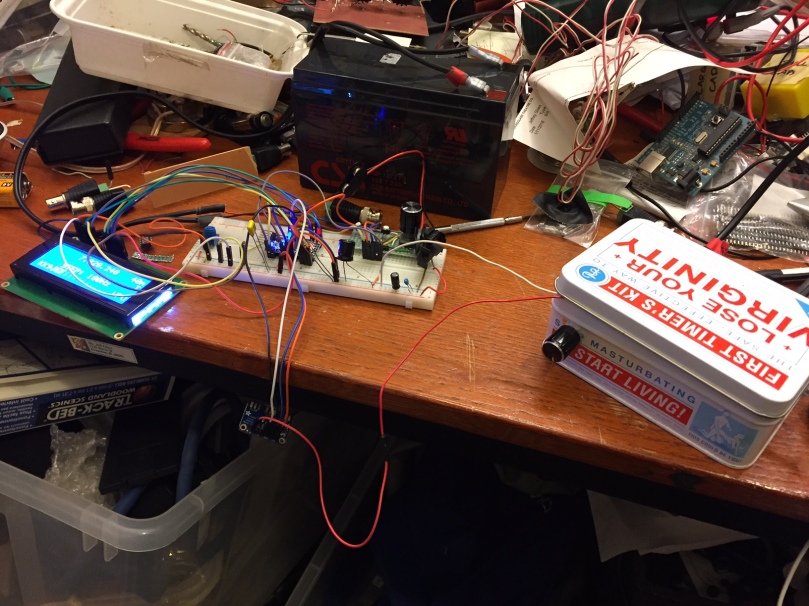
The original Arduino code was designed to make use of a 16×2 LCD display to display the current frequency, as well as licensing information according to the 40m band plan. Since I’ve already been playing with an LCD display on another ongoing project, and since I wanted this to be a simple and durable bit of kit, I wrote a bit of code that instead flashes the current frequency in morse code on a panel-mounted LED. The display is triggered by the press of a button. The number of digits to display is configurable. I’ve found that just displaying the three kilohertz digits is plenty (I don’t need to be reminded I’m on the 7 MHz band every time, and I don’t need precision better than KHz for simple operating). As always, you can see the code on Github.

IMG_1184
The internals of the transceiver. The two green perf-boards are an experimental audio filter to be documented later. The 40-9er board is bottom-left, the K2ZIA board is bottom right, and the small black board on the upper right is the rotary encoder mounted to the front panel.


The full schematic of the original Forty-9er as well as the necessary mods can be found on Farruk K2ZIA’s website. The only additional hardware changes I made were to wire an LED and a 1k resistor between Arduino pin 14 and ground for the LED, and an SPST button between Arduino pin 4 and ground to trigger the frequency display. Like the original code, depressing the encoder changes the tuning rate, though I modified the possible step values to be only 1000Hz, 100Hz, and 10Hz, in that order. 1KHz is useful for zooming around the band, 100 Hz is useful for tuning a specific signal, and the 10Hz step is mostly for resolving SSB/DSB/AM signals cleanly.

On the rear of the radio are the BNC antenna jack and the power pole power input. (Useful tidbit – a pair of connected 30A powerpoles fit neatly in the cut-out for a VGA connector!) I’ve yet to fashion a front-panel, so the connections on the Forty-9er board for a key and headphones are directly accessible.

img_0950

I’ve had the rig out to the park a handful of times now, and it sounds good! Like my other direct-conversion NE602-LM386 experiments, the audio quality is great, but broad as barge, so selectivity suffers. The sidetone is clean, at around 700Hz, from the Forty-9er’s little BJT oscillator. I enjoy being able to tune up into the phone portion of the band and listen to SSB QSOs and nets and such, which provide a good sketch of current propagation conditions. Being able to quickly switch between tuning steps is helpful, as I tune around and try to find someone sending CW slow enough for me to keep up.

IMG_1185.JPG
The top of the rig. Not fancy, but functional.

The only major limitation of the rig is that, with only a single-resonator input bandpass filter, out-of-band signals can get into the radio and cause interference. Specifically, World Harvest Radio WHRI, who maintain and 500KW (no that’s not a typo) transmitter in South Carolina, is often audible everywhere on the dial, which is distracting at best. A stiffer bandpass filter will be necessary soon. I’ve also been experimenting with a peaked audio filter to help with reception of CW, but that’s still experimental.

The unit puts out about 3 Watts, which proved to be enough to make my first CW contact and, over the weekend, my second. The gentleman on the other end this time was Gary N4PIR, who was running 5W on his FT-817 into a trapped vertical. I think a little afterburner would be helpful on my end, as we were definitely fighting QSB. But that’s a later project.

Hear you on the air!

73

Giving the Virgin Some Mobility

As wonderful as it was to ‘complete’ the Virgin Receiver and have a set of ears to start listening on, more and more I find myself wishing for the ability to change frequency and explore the 40m band a bit. To that end, I’ve been experimenting with hooking my Si5351-Based VFO directly to the Virgin as an easy way of giving it the ability to QSY.

(The VFO, as it happens, has a few more features nowadays, including being able to act as  WSPR beacon and having an auto-CQ mode. The code, as always, is on Github.)

Here’s the receiver as built:

schemeit-project(1)

Jason NT7S dropped a hint in one of his older blog posts that the Ne602 likes to see about 300 mV p-p when being driven externally, and that a 10dB pad could be used to bring the Si5351 down to this level. To that end, I put together a quick Pi-attenuator consisting of one 120-Ohm and two 150-ohm resistors.

IMG_0549
A tiny 10dB pi-attenuator.

The attenuator plugs directly into the receiver where the crystal X1 usually sits, in a little 1×3 piece of female header. The output of the 10dB pad plugs into the side of the header that’s connected directly to pin 6 on the NE602; the ground on the attenuator plugs into the other side of the header, and is therefore connector to ground on the receiver.

The longer red and white wires you can see attached to the pad connect to ground and the CLK0 output of the Si5351. Here’s the current setup, spread out on the bench.

IMG_0546

It’s already quite successful! I can scan up and down the 40m band and pick out CW signals pretty well. SSB signals are faint and pretty un-hearable. Unfortunately, for some reason, my receiver has also turned into an AM radio:

I think some kind of high-pass filter is in order here. There’s always been a bit of AM bleedthrough with this receiver, but given that the AM stations are attenuated by the RF Pot on the receiver, it seems like most of this signal is coming in through the antenna and not, say, bleeding into the audio amp.

Hear you (all around the band) on the air!

73


“The Virgin” – A DC 40M Receiver

My first HF receiver project is complete.

It’s not fancy. It’s rock-bound with no ability to QSY. It only has a single RF gain control up front. It’s direct conversion, so it hears all signals on both sides of its frequency. It’s bodged together and probably not super durable.But it’s my own, made from scratch, and I couldn’t be more happy. So without further ado, here’s the finished product:

IMG_0043
The Virgin Receiver – safe for use, if not safe for work.
I received this (scandalous!) container in a White Elephant gift exchange at a holiday party this Christmas, and I immediately thought it would make a good home for a radio. It seems a fitting case for the receiver that’s taking my homebrewing virginity.

schemeit-project(1)
The Virgin DC Receiver. Two IC’s and a power regulator. One knob. No fuss.
The circuit is nothing particularly new: it’s based, as I’ve said before, on the work of Dave Richards AA7EE, some fine projects from GQRP, and a very useful document from Bill KV2AWC. The unit is a direct-conversion receiver based around the ubiquitous NE602/NE612  mixer/oscillator IC and an LM386 audio amplifier circuit. Gain is controlled solely by the RF gain pot in the front-end. I find this provides more than enough gain control. There’s also a position for a jumper to boost the audio output from the LM386, but with the amount of RF noise in my apartment, this proves more detrimental than helpful. I may turn that jumper into a switch if experimentation shows its use.

The only filtering present is the handful of passives that sit between the NE602 and the LM386, filtering the audio a bit between converting to baseband and the audio amplification stage. A little experimentation showed that the present passives only seem to round off higher audio frequencies, say about 6 khz. They’re not really meant to enhance selectivity, but just to reduce noise introduced by signals further away from zero beat.

IMG_0045
A naked view of the inside of the receiver. Avert your eyes, children!
I found some nice panel-mount BNC connectors at our local Fry’s electronics, and fitted some Anderson Powerpole pigtails as a power input. (Pro-tip: if you use Powerpoles regularly, as I do in my theatre job, get yourself a ratcheting crimper. Less than $40, will change your life.) There’s a 1/8″ jack attached to one side and the RF gain control is mounted up front. The whole thing weighs maybe half a pound.

Signals come in clear and hot on this thing! With minimal audio filtering and just a basic front end filter, it’s pretty wide open, but that’s kind of the point – at this point, I’ll take sensitivity over selectivity. Particularly up in the QRS part of the spectrum, I’d rather be able to hear the one guy who’s within 3kHz of my crystal than lose him. Remember, this thing is rockbound, so changing frequencies means swapping in new crystals.

The receiver has gone through several revisions and adjustments in the past couple months. See the original post, changes to the front end, and some power problems for those adventures.

While I’ll probably never really be ‘done’ with this receiver – with tinkering projects, are we ever really done? – it feels great to have it packaged up, in a case, and usable. It’s freeing to have something complete enough to show off.

Hear you on the air!

73


On the Importance of Fiddling and Good Power Supplies.

Troubleshooting continues apace on the new NE602-based direct-conversion receiver. As I mentioned in the previous post about it, the receiver develops and unfortunate, LOUD squeal whenever the 10K audio gain pot at sits between the NE602 and the LM386 is advanced past about the 20% position. This is a terrible impediment to reception, so I’ve been working on eliminating this problem.

TL;DR: The receiver is a whole object tied together by its power system. Good power and a good ground are important.

My suspicions centered on the LM386 chip – after all, an audio amplifier with a couple of feedback caps seems like a prime candidate to turn itself into an audio-frequency oscillator.  This, as it turned out, was a red herring – I’d like to publicly apologize to the LM386 for ever doubting it.

The first step I took was to meter the potentiometer’s resistance at the setting just below squealing, and to replace the pot with two resistors that replicated the resistance at this setting. A little fiddling showed that the squeal could still be induced by varying these resistances slightly, which was encouraging – the problem was somewhere else in the circuit, and not a phenomenon of the pot itself.

So I took an entirely different tack to connect the NE602 and the LM386. The 0.01µF cap in series with a 10K pot was derived from a number of other designs, but it seemed worthwhile to utilize the complementary outputs from the NE602 as a means of input to the LM386’s complementary inputs. I stole this linkage directly from the EMRFD. The NE602’s pin 5 is connected to the LM386’s pin 3 through a 220nF series cap with a 10kΩ resistor to ground. Similarly, the mixer’s pin 4 was connected to the audio amp’s pin 2. Both lines were tied together with a 100nF cap.

FullSizeRender
You can see the three new blue caps that sit between the NE602 and the LM386, a well as the large white jumper bridging the 10uF cap to pin 8 of the LM386

Long story short – no help on the oscillation-front, but a little more stability in the gain, it seems?

Next, I set about fiddling with the feedback circuitry for the LM386. As the datasheet shows, there are gain configurations from 20x to 200x gain with a simple RC network between pins 1 and 8. My original configuration had a 10µF electrolytic cap in between these two pins. I tried replacing that with a 4.7µF cap plus a 2kΩ resistor, leaving those pins totally unconnected… in all configurations, it was possible to get the audio to oscillate. So no such luck there. I put the 10µF cap back in, and joined it to pin 8 with a small piece of female header, so that I could insert various resistors in that position to adjust the gain later, if need be.

Oddly, both reception gain and AM bleedthrough is increased whenever I touch the leads of the gain resistor. The AM bleedthrough sounds a lot like what happens when you touch one of the un-connected leads of the LM386, but why do I hear CW signals a lot clearer as well?

It was this oddity with the gain resistor that gave me the vital clue. “Well,” I thought, “maybe touching and fiddling with the other components will give me some clues.” I just played around on the board for 20 minutes with it powered on, tying this point to ground, putting that point high through a resistor… interesting things happened, but squealing was still very much a possibility. That is, until I happened to accidentally pull the oscillator crystal out of its holder, and the squealing stopped.

“Now that’s odd!” I thought. “I assumed this problem existed entirely in the audio half of this receiver. Why should removing the crystal, and thereby halting oscillation in the mixer, have any effect?”

A little poking around with a meter and a scope and I had my answer – the little (used!) 9V batteries I was using as a power supply for this receiver were woefully under-powered. Under load (i.e. with audio coming out of the headphones), the voltmeter read about 7.3V, and dropped by about 10 mV per second. Oscillation seems to occur when the voltage  drops too low. (I’m measuring voltage as a proxy for available power, in this case, I think.)

So, after borrowing a nice big 13.8V, 8aH SLA battery from work and bodging together a quick-connect to battery-clip connector… wait for it…

No more motorboating! (And a bunch more audio output to boot.)

FullSizeRender(3)
Used 9V batteries just won’t cut it! The big SLA battery provided great power and more audio output.

I still need to boast the overall gain of the system, since it takes a pretty strong signal to get into the receiver, but at least it’s not likely to HOWL in my ears!

Next thoughts: to increase gain, perhaps stealing the alternate LM386 gain configuration from AA7EE’s WBR Recevier, or one of the broadband, ~18dB IF amplifier designs from the original BITX or QRPKit’s variant.