Bench Report – HamRadio360 Podcast, Beach-40, SigGen, Power Meter Projects

A few weeks, back, I spent about half an hour chatting with Jeremy, KF7IJZ, for a listener-projects segment on the HamRadio360 Workbench podcast. That episode just went live this morning, if you want to take a listen online. Jeremy and I had a swell time chatting about the QST 40-9er Transceiver project I built awhile back, and ended up packaging with a laser-cut faceplate.

Seeing the podcast pop up got me thinking – from the last few months of posts, you’d think that I’d been spending all my time operating and that my bench was empty. Not so! There are three major projects milling about the bench these days. None are complete enough to merit a full post, but consolidating them all in to one post feels right.


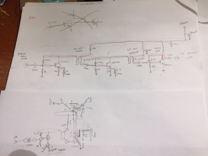
First on the bench is the continuation of my Beach 40 Transceiver project, that I’ve been working on since the Fall. I’ve been making steady progress recently on the penultimate stage, the RF amplifier, which will take the ~10dBm modulated voice signal from the balanced modulator and turn it into ~33dBm (2W) of RF output power to send to the LPF and out into the world. The amplifier is a three-stage design, with a 2n3904 buffer feeding a BD139 driver and another BD139 final.

IMG_2291.JPG
Beach40 PA Schematic and Layout, in Graphite-O-Vision.

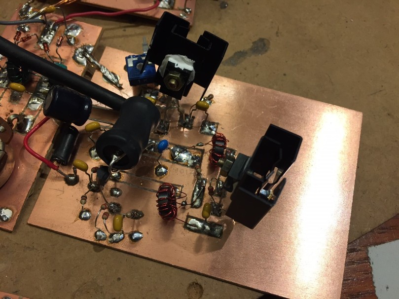
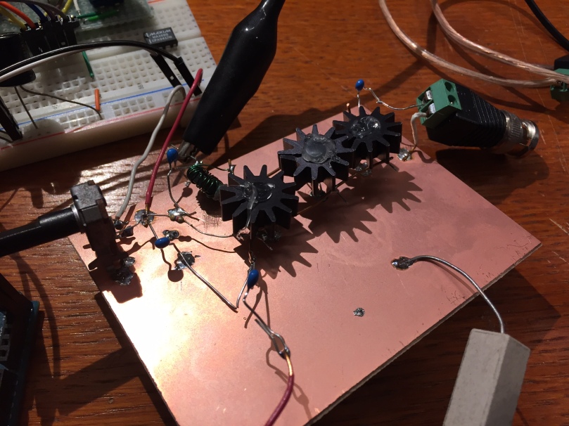
The module is assembled manhattan-style on single-sided copper glad, just like the rest of the project. The layout surrounds the +12V-on-transmit bus down the center of the PCB… more on that error later.

IMG_2155.JPG
The Beach40 PA mid-assembly – you can see the +12VT buss running down the middle, and the buffer and driver stages starting to take shape.

The module assembly and testing went fairly smoothly – using a variable-voltage power supply, it’s easy to vary the output power of the amplifier, and to observe the changes in PA heating that this causes. You can see the two large screw-on heat sinks on the BD139’s in the following pictures, as well as the the large ferrite bead which feeds the Final. There’s also a chunky 100uF cap at the DC input to the board for additional decoupling.

IMG_2288.JPG
The assembled Beach40 PA.


The problem I’m having now is the same one that plagued me way back in my assembly of the Virgin Receiver, my first first homebrew receiver: this amplifier would really love to be an oscillator. With the PA voltage set at 12V, any time the signal imput is sufficiently strong, the PA will fall hard into oscillation, and won’t stop until the PA voltage is brought way down or cut. I’ve been experimenting with emitter degeneration for the final BD139 (the original schematic has the emitter directly grounded). That’s helped, but not much. I’ve also changed the RF-carrying wires from hookup wire to coax, to mitigate feedback through other modules. Another help, but so far, the oscillation problem is still there. The next step will be to move the modules themselves around, to limit the amount that the high-power RF coming from the PA has to pass by earlier stages of the transmit chain (VFO, mic amp, balanced modulator) to try to eliminate feedback that way. Fingers crossed!


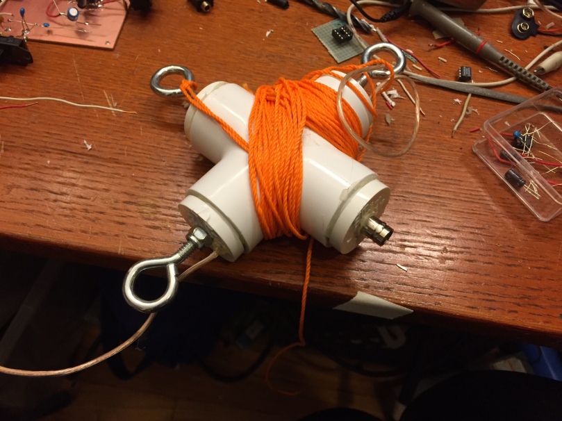
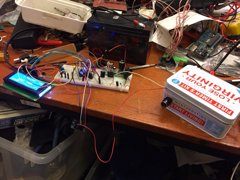
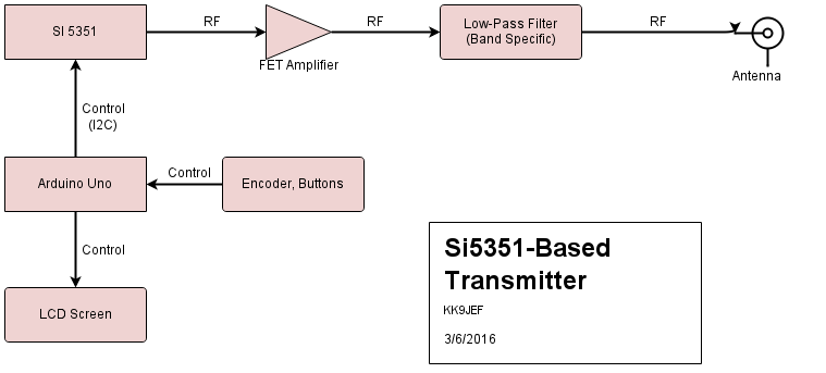
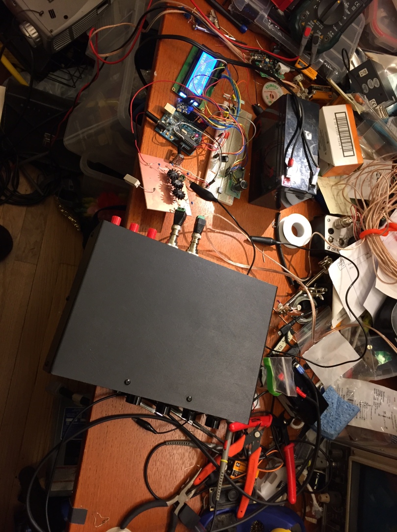
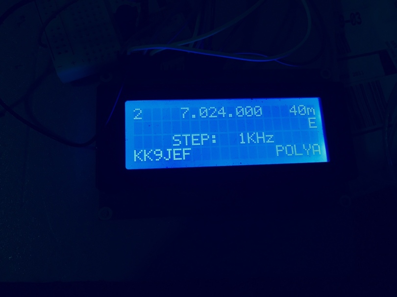
Next on the bench is a repackaging of an old project – my SI5351-based “VFO,” which for the better part of a year has been serving as my primary signal generator for experimental projects, spread out in all its Al-Fresco glory on a breadboard. With the amount of troubleshooting I’ve been going through on the Beach 40 project, I’ve decided to finally box up the SI5351, Arduino, and display into a proper project box, and make the thing a real SI5351-based Signal Generator. The schematic is essentially unchanged (minus the PA) since I used the project in my SI5351-based transmitter project, which is reproduced below:

CW Transmitter sCHEMATIC

To that end, I purchased an inexpensive nibbling tool and an expensive project box from the local Fry’s electronics, and have been working in the past couple weeks to marry the spread-out guts of the previous project with the clean lines of the enclosure. Biting out the large hole for the display 1/8″ at a time was time-consuming and strangely soothing.

At this point, the display and Arduino are connected, but I have yet to wire the two control buttons, rotary encoder, and Si5351 breakout board back into the Arduino. I also need a provision for getting the signal out the front of the darn thing, so I’m waiting on a shipment of SMA connectors and a jumper to go from the SI5351 breakout board to the front panel. So far, so good.

The code for this project is still on Github.


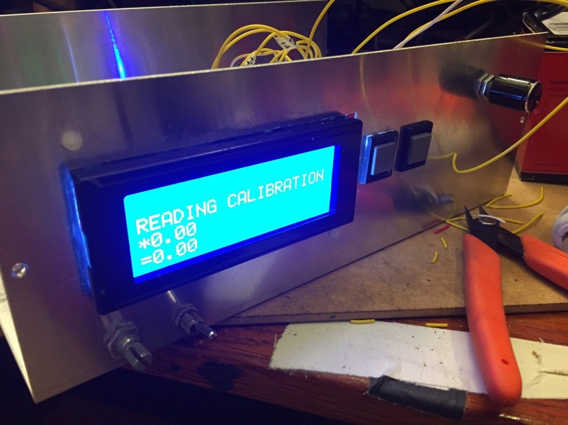
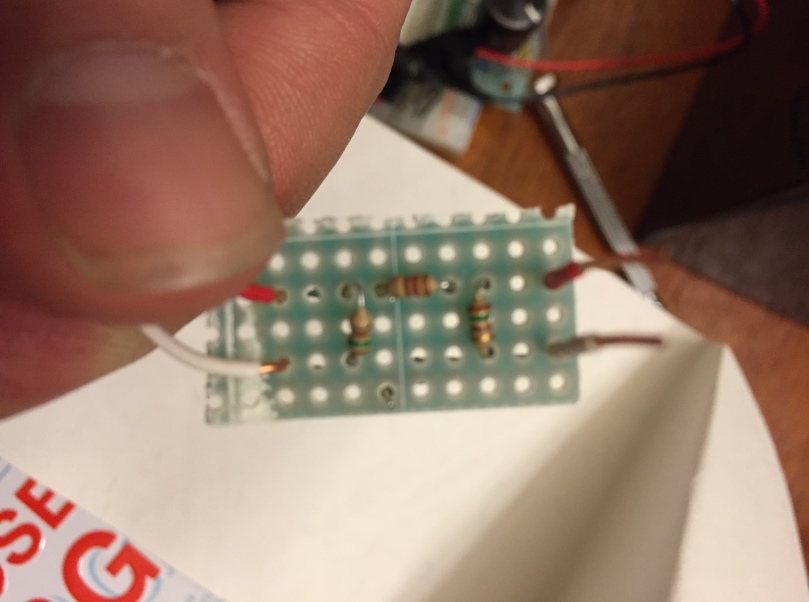
The last project on the bench is an RF power meter circuit, based on a circuit by W7ZOI from 2001. While the old scope-probe-across-a-50-ohm-load technique has proven very useful, I’ve found myself wanting a way to more reliably measure RF power at low levels, and to do it in a way that could be interfaced to a microcontroller or computer. To that end, I plan on using the W7ZOI circuit connected to an Arduino, much like Vu2ESE’s Sweeperino, to make digital power measurements.

IMG_2292.JPG

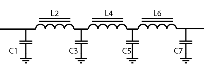
I rolled a little PCB for this project from OSHPark, and since that service provides PCBs in multiples of 3, I figure I’ll connect one board to an analog meter (for that old-school feel), one to an independent Arduino (for digital measurements), and embed one inside the SigGen project, for marrying signal generator and power measurement at specific frequencies. This last project, I figure, will be especially useful for examining filter behavior at HF and piping the information to a PC for display an analysis.


So that’s what’s on the bench at the end of March 2017. All of these will hopefully merit full posts in future as the projects come to fruition, but for now, the is the smorgasbord that is my bench.

Hear you on the air!

73

An Si5351-Driven QRP Amplifier

This work follows directly on from my initial thoughts on an Si5351-Based Transmitter. Check out that post for background.

This project ulimately got packaged up into the SI5351 Signal Generator/VFO.

This week I finally got around to improving the transmitter/amplifier I started work on back in March. With a shipment from KitsAndParts, I replaced the J110s that had been part of this amplifier and replaced with BS170s. The differences between the parts are striking – the J110 is a general-purpose JFET (which is by definition a depletion-mode FET) with a rated power disipation of a few hundred milliwatts. The BS170 is a fast-switching enhancement-mode MOSFET with a rated disipation of 800 mW.

Here’s how the schematic looks now. Pretty similar to the last time, with a couple key changes:

CW Transmitter BS170

I stripped the heat sinks that had been on the J110s off and threw them on the BS170s. These puppies still do get hot, and even with the ability to dissipate almost a Watt, I think they’d not be pleased too much heat. The heat sinks, plus some thermal goop from Microcenter, are easing my mind a bit.

As built, the amplifier had an output impedance of about 10 ohms at 7 MHz, as measured by the method suggested by W2AEW in this Youtube Video. To bring that up to the standard 50 Ohms, I built a little L-match, using the values suggested by this L-Match calculator, about .43 uH in series with the amp and a little over 1 nH shunted to ground. Because I don’t know the voltage ratings on most of my miscellaneous caps, I put for 4.7nF caps in series to form the fun capacitance. The inductance is 12 turns on a T37-6 (I did some experimenting to find the ideal number of turns). Re-measuring the output impedance (again with the W2AEW method) showed an output impedance of around 47 ohms, which is close enough for my purposes, I figure. I

I also recently bought a little power-supply kit from Ebay, and have been using that to supply the drive current. It’s adorable:

Now, being driven by the Si5351, the amplifier puts out about 1W on a 5V supply, and about 5W on a 12V supply. Not a particularly clean signal, mind – the 5W is as measured in the power meter of an MFJ-949 – but it is an actual 5W!

Hear you on the air!

73

Wind, Antennas, and a First Portable Session

This week I had two radio firsts: trying to put together a halfway decent antenna, and a first portable operating session.

I started by putting together a center insulator a dipole antenna. There are many possible designs online, but I ended up making one with materials I’m familiar with. It’s made of a 1″ PVC cross, four PVC caps, three 1/4″ eye-bolts, some nylon lock-nuts, and panel-mount BNC connector. The whole went together in about half an hour. The PVC connections were surprisingly tight as a press-fit, but they and the eye-bolts are secured with lock-tite and sealed with hot-snot just in case. The BNC connector is soldered internally to a couple pieces of hookup wire, which you can see poking out the sides of the cross. The antenna wires themselves are simply tied to the eye-bolts and wire-nutted to the hookup wire.

IMG_0587.JPG
The dipole center-support. This picture was taken after the fact, hence the pre-cut Nylon cord wrapped around it. You can see the two copper hookup wires poking out either end.

The dipole center, a 200′ spool of nylon wire, some “stakes” for securing the antenna to the ground (really, 8″ pegboard hooks, on sale at Menards!), some zip-ties, and a couple of rice-filled socks as counterweight all fit handily into this small plastic case I had lying around:

IMG_0588

I live only about a mile from Lake Michigan and the beautiful lakefront park space that runs along the East side of Chicago. I figured with the sunny-but-chilly weather we’ve been having this week, the lakeshore on a weekday afternoon would be pleasant to work in and not too packed with people.

I couldn’t find a suitable table or bench close enough to trees to set up under, but then I spotted the convenient height of the sea-wall between the outer lakefront trail and the lake itself. I couldn’t have been any closer to the lake without getting my socks wet!

IMG_0585.JPG
The operating position. There’s a little ledge just on the other side of this wall that was perfect for standing on.

I strung up a portable, homemade 40m dipole (wires cut in advance) as high as I could could into one of the nearby trees – I only got the center maybe 20 feet in the air, but that’s still better than the 8′ the random wire in my home office is. The ends are tied off to stakes near the ground. This made the setup more of an inverted-V than a true-dipole.

IMG_0582.JPG
One of the antenna-wires staked off to the ground. You can see the black coax sloping from the tree to the operating position.

The antenna is fed from ~60′ of RG-58, running into a ZM-2 Tuner for matching, and then via a short RG-58 jumped into the Virgin Receiver. I also brought along the ardiuno-controlled, Si5351-VFO I’ve been working on to allow for the ability to change frequencies, as detailed in my last post. If I’m going to spend the time setting up practically in a lake, I thought it would be nice to actually scan the whole band. Since the VFO rig is still on a breadboard, I was quite spread-out over my little stony operating station.

IMG_0577
Visible here: the coil of coax coming from the antenna; the Virgin Receiver, open to allow the VFO to interconnect; the breadboard with the Si5351 VFO on it; two separate 12V SLA batteries; some nice comfy headphones; and the large red cable-coiler I used to store the dipole wires (a bit overkill).

So now, the moment of truth – I hooked up the batteries, connected the receiver and VFO, did a quick by-ear tune on the ZM-2. I’ve never done something like this before – would it actually be better than my office random-wire? Was it all just a jaunt in the park? In short, would it work?

LIKE HECK IT WORKED!

Especially up in the SSB portion of the band, there were some stations that might as well have been on the other end of a phone call. (This, by the way, confirms that the Virgin can receive SSB and AM as well as CW.) In no particular order, I heard:

  • N8KKR, KA9ZXN and others on the Hams for Christ net on 7.263 (330p Central, Monday-Sat). Not my personal bag, but they seemed a very pleasant bunch.
  • W9DCQ and W4LWW having a nice QSO, between the two of them and some other operators I couldn’t quite copy.
  • KG9O and KK4FZI having a friendly chat.
  • Some other snippets of stations.

The listed stations alone include QTHs in Evergreen Park IL, Columbus OH, Middleton WI, Franklin TN, Grassy Creek NC, and Marion IN. None of them terribly far away in radio terms (the Tennessee locations is farthest at ~500 miles), but a great confirmation that the antenna was clear and working. With a height above the ground of less than 1/4 wavelength, the ideal dipole should have a high takeoff angle and be fairly omnidirectional, and that seems plausible based on results.

In sadder news, I seem to have broken some part of the WSPR functionality of my VFO in consolidating that functionality from two separate programs into one. 1W into the antenna and several repetitions netted be exactly zero receptions, either into this antenna or my office random wire. So it’s back into the code I go. While I’m at it, it would really be worth packaging up the little VFO into its own enclosure – having all those wires flapping about is a bit worrisome for transport!

All in all, a tremendously successful, if very chilly, day by the lake. Now that I know what I’m doing, I suspect it would be able to have the station set up and listening in about 10 minutes, and about the same for tear down. With the days getting warmer all the time, I’m sure I’ll be out there again soon.

Hear you on the air!

73

Giving the Virgin Some Mobility

As wonderful as it was to ‘complete’ the Virgin Receiver and have a set of ears to start listening on, more and more I find myself wishing for the ability to change frequency and explore the 40m band a bit. To that end, I’ve been experimenting with hooking my Si5351-Based VFO directly to the Virgin as an easy way of giving it the ability to QSY.

(The VFO, as it happens, has a few more features nowadays, including being able to act as  WSPR beacon and having an auto-CQ mode. The code, as always, is on Github.)

Here’s the receiver as built:

schemeit-project(1)

Jason NT7S dropped a hint in one of his older blog posts that the Ne602 likes to see about 300 mV p-p when being driven externally, and that a 10dB pad could be used to bring the Si5351 down to this level. To that end, I put together a quick Pi-attenuator consisting of one 120-Ohm and two 150-ohm resistors.

IMG_0549
A tiny 10dB pi-attenuator.

The attenuator plugs directly into the receiver where the crystal X1 usually sits, in a little 1×3 piece of female header. The output of the 10dB pad plugs into the side of the header that’s connected directly to pin 6 on the NE602; the ground on the attenuator plugs into the other side of the header, and is therefore connector to ground on the receiver.

The longer red and white wires you can see attached to the pad connect to ground and the CLK0 output of the Si5351. Here’s the current setup, spread out on the bench.

IMG_0546

It’s already quite successful! I can scan up and down the 40m band and pick out CW signals pretty well. SSB signals are faint and pretty un-hearable. Unfortunately, for some reason, my receiver has also turned into an AM radio:

I think some kind of high-pass filter is in order here. There’s always been a bit of AM bleedthrough with this receiver, but given that the AM stations are attenuated by the RF Pot on the receiver, it seems like most of this signal is coming in through the antenna and not, say, bleeding into the audio amp.

Hear you (all around the band) on the air!

73


Easy QRP Low Pass Filters

With an eye toward getting my rudimentary Si5351-based transmitter on the air, I’ve started putting together a number of low pass filters to knock down some of the nasty harmonics that come with using a clock chip as a frequency generator.

The filters are all based on the designs given by W3NQN in the GQRP technical pages from 2015. (This is another point at which I’m taking design inspiration from the QRP-Labs QRSS beacon.) The paper lists both the target values for each of the toroids and capacitors for a 7-pole low pass filter for each band, as well as the required number of turns for each toroid and an appropriate toroid to use. For this project, since my target frequencies range from about 7 MHz to 14 MHz, I’m using all T37-6 toroids from KitsAndParts.com. The basic design of each filter is the same:

lpf sketch
All these filters are symetrical, for 50-ohms on either side.
Here’s the values that W3NQN gives for low pass filters for the 20m, 30m, and 40m bands:

Band C1, C7 C3, C5 L2, L6 L4
20m 180pF 390pF .773uH .904uH
30m 270pF 560pF 1.090uH 1.257uH
40m 270pF 680pF 1.380uH 1.698uH

Unfortunately, I don’t have exactly the specified capacitors in my kit, so here’s my approximation to these values. (Note that the number of turns is different at 40m than W3NQN recommends, to more closely match the specified inductance). All inductors are wound on a T37-6:

Band C1, C7 C3, C5 L2, L6 (turns) L4 (turns)
20m 1000+220 (series) = 180pF 1000 + 690 (series) = 408 pF 16T = .77uH 17T = 0.87uH
30m 220+47 = 267pF 220+220+100 = 540pF 19T = 1.08uH 20T = 1.20uH
40m 220+47= 267pF 470+220=690pF 21T = 1.32 24T = 1.73uH

Some quick simulations in LT Spice confirms that these little adjustments don’t have an enormous effect on the filter’s behavior. On 40M, for example, it has the effect of moving the cutoff frequency down maybe 100 KHz:

40m LPF Filter as Built
The behavior of the 40m LPF as constructed with the parameters above. Note the nice knee just under 10MHz and that the attenuation is around 40dB at 14Mhz, the second harmonic for this band.
So far, I’ve only constructed the 40m filter. It’s built on a little 2.3cm x 10cm piece of coppper clad. (I’ve got a bulk stock of 7cmx10cm pieces, which cut nicely into threes to make little projects like these).

IMG_0537
The 40m filter as built. I love these little screw-on BNC connectors. There’s probably some RF leakage because of them, but they’re so easy to apply and use. And it makes changing male and female BNC connectors as necessary a breeze.
The filter seems to be working great – a little qualitative examination with an oscillloscope shows that the filters are smoothing out the waveform at 7 Mhz quite nicely. Above that, the attention seems to match the slope predicted in the simulation above.

With this filter on my little homebrew transmitter, I finally made my first (official) WSPR contact… but that’s a story for another post.

Hear you on the air!

73

Si5331-Driven Transmitter – Beginnings

In Spring, a young man’s fancy turns to thoughts of transmitters. Having recently completed a receiver, and with the weather starting to warm a bit, I’ve got an itch to actually get on the air and talk back to the stations whose code I can now (slowly, painfully) decode.

Re-purposing some hardware and code from my DDS VFO project, I’ve been working on on a digitally controlled CW transmitter based around an Si5351. This is by no means an original thought, and my designs are largely based on Qrp-Labs’ Ultimate3s Kit. You can check out that original design over on the QRP-Labs site, under the PCB assembly instructions.

Essentially, this transmitter uses an Si5351 DDS clock chip to directly synthesize the desired output frequency, at up to 200 Mhz. This frequency is then amplified by a simple FET amplifier to approximately a 1W output level, then passed through a low-pass filter and out to an antenna. The Si5351 is controlled over i2c by an Arduino Uno, which has an attached LCD, a rotary encoder, and a couple buttons for frequency and band control. The updated code for this project is on Github.

Here’s a block diagram of the transmitter:

Si5351TransBck-3-6(3).png

The nice thing about this design is that the main frequency-dependent component is the low-pass filter; the Si5351 should be stable enough for CW contacts up to at least 50MHz. (Without an ovenized environment for the reference clock or some GPS disciplining or similar, there’s still a little drift and inaccuracy, but I don’t think it will be noticeable.) Above HF, I’d expect to see diminishing returns from the FET amplifier. But switching HF bands should just mean switching LPF filters and pressing a button on the VFO.

Here’s the circuit as constructed, up to where the LPF would go:

CW Transmitter sCHEMATIC
The simple Si5351-based transmitter, with a 3-FET amplifier.
Let’s walk through the circuit starting from the signal generator and working out toward the antenna. The output of CLK0 on the Si5351 is coupled into the amplifier with a 100nF cap. This drives the gates of three J110 FETs, and is biased upward by a voltage divider formed by a 10K pot and a 4.7kOhm resistor between 5V and ground. The power end of this voltage divider is bypassed to ground with a 100nF cap.

Power for the amplifier is fed from a nominal 12V (or lower) through an RF choke, in this case 25T on an FT37-43, into the FET drains. A 100nF cap here helps further bypass RF to ground at this point. Output is taken off the drains through a final 100nF cap. The FET sources are grounded.

While an actual RF transistor like a BS170 would likely be ideal, I had a bunch of J110 FETs in my bin after my last trip to California, so that’s what I used. They’re only rated for about 300mW dissipated power, so I’ll need to be careful with my heat sinks and duty cycle until I can replace them with something a little more sturdy.

IMG_0393
Three J110 FETs with their heat sinks on a piece of copper clad. In the back you can see the PA power coming in through the black alligator clip via the small RFC. The bias pot is on the left, signal comes in on the red wire on the bottom, RF out via the BNC connector on the right. The big white box down in the bottom is a 51 Ohm, 5W resistor I was using as a basic dummy load for testing
Preliminary results are encouraging – I hooked the output of the above circuit directly to a dummy load with no low-pass filter and ran the clock generator at 7.050MHz. I assessed power by reading off the peak voltage on an oscilloscope.I started with just 1 J110 and a 5V PA supply instead of 12V. This yielded about 9V peak-to-peak, or 200mW into 50 ohms. Installing the other two J110s bumped the output up to 10V P-P, or 250mW. Finally, after installing heat sinks on the FETs for safety and taking the supply voltage directly from a 12V SLA battery (~13.2V), the output hit 22V P-P, or 1.2W into 50 Ohms.   This last reading was verified with the power meter on an MFJ versa tuner.

IMG_0376
The transmitter spread out on the bench, with the display and Arduino at the top, the amplifier visible on the copper-clad in the middle, and a bulky MFJ tuner at the bottom acting as dummy-load and power-meter.Power provided by the 7Ah, 12V SLA battery at top-right.
I’ll need to put a little elbow grease into low pass filters before putting this on the air, because even on a scope the signal looks a bit gnarly. But first the first time, I’m responsible for 1W of Homebrew RF power. Watch out!

73


Fried Green Arduinos

It was only a matter of time until something blew up. And last night, it was TWO things.

The first one was my own darn fault  – I’ve been playing around with some simple transistor amplifier circuits, and mis-read one of the transistor data sheets. When I hooked it up a 12V power source… BANG!

IMG_0064You can see the TO-220 package there, literally split in half by the power of electricity. Zam zam! Turned out I had grounded the emiter and applied 12V to the base of the transistor. It blew apart in my face in a shower of sparks.
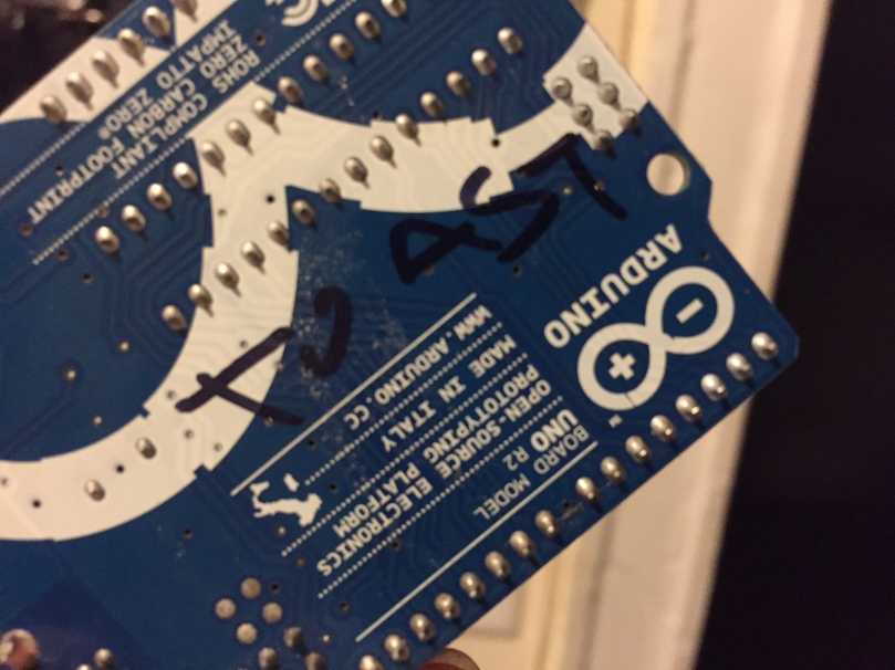
So, I desoldered that transistor and replaced it with a little J110 FET I had a pile of from my last trip to California. While messing around with the supply voltage, I kept switching a clip lead back and forth between 5V coming out of the 5V rail on an arduino an 12V directly from and SLA battery. Unfortunately, at one point, I disconnected the clip from the circuit and ended up connecting the Arduino directly to 12V…

IMG_0069

You can’t make radios without breaking a few toys. Thankfully, the Si5351 breakout and the nice LCD screen I had hooked up were unscathed. Another sacrifice to the radio gods.

73

Update 2/29: I’ve toasted another one! I’ve been using my old Duemilanove to work on a transmitter project, and apparently relying on its little 5V regulator to power an LCD screen, an Si5351 breakout, and provide bias current to the finals was just too much for the little thing….

DDS Output Screen in Polyakov mode.

40m Direction Conversion Receiver “In the Polyakov Style”

tl;dr: My build of KE3IJ’s DC-80 Receiver for 40m works! Building radios is fun!

I stumbled across KE3IJ’s version of an RA3AAE-style (V. Polyakov) receiver some months ago as I started looking into homebrewing my own receiver/transceiver. I figured a direct conversion receiver would be a good place to start, as it would give me immediate reception with a simple pre-selector filter, mixer, and audio amplifier. RF filter designer, and IF filter design in particular, scares me a bit as a new radio builder, so I figured a superhet was probably a little too advanced to start with. So when I stumbled across KE3IJ’s version of a direct conversion receiver that seems to have reduced some of the issues with direct conversion receivers (microphones, AC or ‘common mode’ hum), it seemed like a reasonable place to start. You should absolutely read his full write-up on his build.

Here’s KE3IJ’s original design:

KE3IJ's DC-80 Receiver
Original Design of KE3IJ’s DC-80. Some revisions crossed out at a later date.

The central, exciting part of the DC-80 is that the VFO is tuned to half the operating frequency. That is, to tune in a signal at 7.040 MHz, you would set up the VFO to oscillate at 3.520 Mhz. Which explains why the original design lists the VFO range as 1.79-2.0 MHz for reception on 80 meters.

Rick has some interesting theories (and has done some experimentation) as to why the half-frequency VFO works that are well worth reading. After trying some different mixer options and settling on the two pairs of anti-parallel diodes, he concludes that what’s actually happening has little to do with “frequency doubling” or somesuch. Rather, an incoming signal (at, say, 7.0 MHz) mixes with a half-frequency VFO (in this case, at 3.5 MHz) to produce two signals at 7+3.5 = 10 MHz and 7-3.5 = 3.5 MHz. This copy of the original signal at half the frequency (3.5 Mhz) then mixes again with the half-frequency VFO (3.5 Mhz) to produce a baseband signal (“0 Hz”).

Seems like a plausible mechanism to me… and regardless (spoilers), it works!

One change I made was to replace Rick’s “quick and dirty” VFO (since I don’t have an AM radio to tear apart at the moment) with the Si5351 derived VFO I previously built. I’ve upgraded the Arduino code (available on Github) with a band-select button to jump between the various HF bands, and a mode button to change between some operating modes. For this project, I mostly left it in “Polyakov” mode, which just means the DDS VFO is outputing half of the frequency displayed on the screen.

DDS Output Screen in Polyakov mode.
Arduino-controlled DDS in Polyakov mode, outputting half the displayed frequency

Sidebar: I added a few additional features which I was updating the Arduino code. When you press the Band Select button, if you’re within one of the HF bands, the Arduino will remember your current tuning and return to that frequency when you cycle back to that band. Also, the “E” in the upper corner of the above picture indicates that only Extra-class licensees may transmit at the displayed frequency: I baked license-permissions into the code as well. Being only a General, I wouldn’t be allowed to transmit here!

The other other change I made was to implement a 40m band pass filter instead of the original 80m filter. I just ripped the values straight out of Rick’s original suggested for a 40m bandpass. I really don’t quite understand it, but it does seem to isolate the 40m band nicely.

So, with those changes in place, the actual schematic became:

Schematic for 40m DC Receiver

Which turned into the following pile of spaghetti on copper-clad and a breadboard:

Assembled 40m Receiver

With the solder cooling, I plugged a long bit of wire into the antenna input and set up my little 40m Pixie on the YL’s desk about 6′ away with a 7.114 MHz XTAL. I tuned the VFO to 7.114.500 and clicked the key on the Pixie, and…. Sound! A glorious 500 Hz tone! What a beautiful feeling, when something scratch built works. Flush with excitement, I hauled the receiver out to the backyard and plugged my ~1/4 wavelength bit of wire (10m) antenna, and boom, strong signals coming in from about 7.0 MHz to 7.060 MHz. The fact that this was during the ARRL November CW Sweepstakes meant that there were many signals on the air to listen to, many of them running 100s of Watts for contest’s sake.

Not bad for a first outing! Several issues exist, of course, in no particular order:

  • Having the 9V battery biasing the audio pre-amp transistors does increase the signal volume in my earbuds by maybe 2-3 dB, but it also increases the background noise volume by maybe 10 dB! With that 9V no longer in the circuit, signals appear faint but audible, and noise drops almost to nothing. I haven’t gone back and confirmed that it’s not an assembly error, but this does not seem like the desired behavior.
  • Sadly, the work lights in my office are very RF noisy. I have three 24″ fluorescent fixtures mounted above my desk, and when they’re on, the antenna and receiver both pick up ungodly noise.
  • Something in either the VFO, the rotary encoder, or the backlit LCD display makes an awful THUMP in the audio whenever I change frequencies. More experimentation will be necessary to figure out where that’s coming from. Initial theories are the I2C lines controlling the display, or maybe they’re an artifact of the frequency change on the Si5351 itself.
  • I suspect that driving the diode mixer directly from the output of the Si5351 breakout board may not be pushing the diodes into conducting for much of each cycle… Some kind of buffer may be necessary.

Hear you on the air!

73

Santa in September

Santa (UPS) delivered some goodies today! Here’s what was in the mail sack:

Goodies from Ebay & Adafruit
Lots of toys on the desk! All nicely package and bubble wrapped.
  • From Adafruit
  • From KC9ON (3rd Planet Solar)
    • A six-pack of useful 40m Crystals – 7.030, 7.050, 7.055, 7.110, 7.114, and 7.122. A piece of cake to order through ebay, and John shipped them out in no time. Came packaged in a nice mailing envelop with invoice – would gladly order from this source again.

73

Si5351 DDS

Update: for more information on the evolution of this project, see First Steps in Arduino Driven DDS and Si5351-Driven Transmitter.

I’ve ordered a breakout board for Silicon Labs DDS chip, the Si5351, as a starting point for working with signals and forming a homebrew VFO. I think the first thing I’d like to try is putting together a “Polyakov-Style” direct-conversion receiver using KE3IJ’s excellent descriptions, probably for the 40m band, as a place to start. I’ve already got the bulk of the parts in my junk-bin, and a couple toroids are on their way

The folks at Etherkit have put together a very full featured library for the Si5351; I just wish it wasn’t so big! It eats up about 3/4 of the space on an Atmega328 by itself, which doesn’t leave a whole lot of room for other programming. Maybe it’ll be worth me implementing i2c of the Si5351 directly, since I don’t think I’ll be using a lot of the features of the Si5351 Etherkit library to start with.