SI5351 Signal Generator

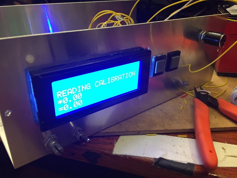
As I alluded to in my March bench report, I’ve been working on packaging up my old SI5351 VFO that sat on a breadboard for two years into a functional signal generator for the bench. That project is now essentially complete, though there are a couple of planned improvements in the works.

IMG_2249

The heart of this project is a Silicon Labs Si5351 clock-generator IC, on a little interface module from Adafruit.  With an I2C interface, it can output square-wave signals at roughly 6dBm anywhere from 8Khz to 160 MHz. This nifty little chip has been around for a few years, and has been used in many a homebrew radio rig, including the work of N6QW, N2CQR, M0XPD, and other. Jason NT7S was essentially in building some of the earlier Arduino-friendly libraries for controlling the Si5351. With such a wide frequency range and the confidence that comes from XTAL-derived, PLL frequency generation, this little chip has breathed life into rigs both new and old.

With the hardest part of building a SigGen (actually producing the darn frequency) neatly packed away in silicon, what remains for a builder is to wrap the thing in packaging to promote ease of use and flexibility. That’s where the fun of this project lay. The parts list ended up like so:

The project box and the LCD display were the most expensive parts of this build by a wide margin, although both would be available for quite a bit less with a longer lead time from oversees.

The SigGen has 4 different software modes:

  • VFO – The primary output frequency matched the displayed frequency. Frequency steps are 10kHz, 1kHz, 100Hz, and 10Hz.
  • Test – Same as VFO, but steps are 10MHz, 5 MHz, 1 MHz, 500kHz, 100kHz, 10kHz, 1kHz, 100Hz, 10Hz, and 1Hz.
  • Polyakov – Primary output frequency is half of the displayed frequency, for experimenting with half-frequency-driven mixers. Step size is the same as VFO mode.
  • BFO – Adjusts the secondary output frequency, for using the SigGen to drive a Superhet directly. Steps are the same as in Test mode.

The SigGen’s three pushbuttons (one built into the rotary encoder and two next to the LCD screen) do essentially the same thing in each mode:

  • Encoder: Changes the frequency step size, per the step options above.
  • Mode: Changes through the software modes, per above.
  • Band: Advances to the next highest Amateur band frequency, to aid with band-changes especially in VFO mode. For example, if the current frequency is 5.72MHz, pressing the Band button sets the frequency to 7.0Mhz, the bottom of the 40m band.

There are still a couple improvements I’d like to make, namely replacing the cheapo detent-based rotary encoder with a nice smooth continuous one, which can be had for about $10 on eBay – using a detent-based encoder as a VFO is a pain in the patoot. I’d also like to implement a sweep functionality to sweep through various filters, but that would require a bit more UI work as well.

This gadget has been complete on my bench for a month of so, and has already been useful in working on my variable-bandwidth superhet… but that’s a story for another post.

Hear you on the air!

73


Bench Report – HamRadio360 Podcast, Beach-40, SigGen, Power Meter Projects

A few weeks, back, I spent about half an hour chatting with Jeremy, KF7IJZ, for a listener-projects segment on the HamRadio360 Workbench podcast. That episode just went live this morning, if you want to take a listen online. Jeremy and I had a swell time chatting about the QST 40-9er Transceiver project I built awhile back, and ended up packaging with a laser-cut faceplate.

Seeing the podcast pop up got me thinking – from the last few months of posts, you’d think that I’d been spending all my time operating and that my bench was empty. Not so! There are three major projects milling about the bench these days. None are complete enough to merit a full post, but consolidating them all in to one post feels right.


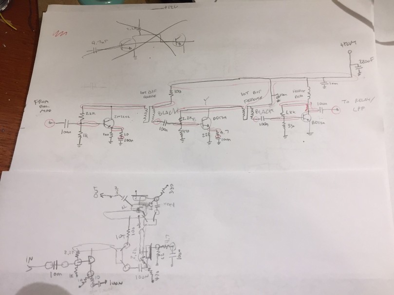
First on the bench is the continuation of my Beach 40 Transceiver project, that I’ve been working on since the Fall. I’ve been making steady progress recently on the penultimate stage, the RF amplifier, which will take the ~10dBm modulated voice signal from the balanced modulator and turn it into ~33dBm (2W) of RF output power to send to the LPF and out into the world. The amplifier is a three-stage design, with a 2n3904 buffer feeding a BD139 driver and another BD139 final.

IMG_2291.JPG
Beach40 PA Schematic and Layout, in Graphite-O-Vision.

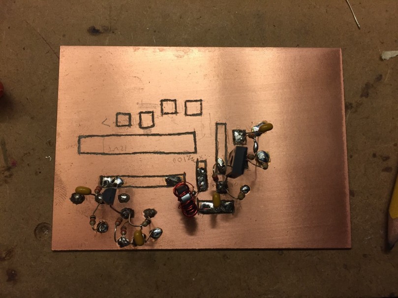
The module is assembled manhattan-style on single-sided copper glad, just like the rest of the project. The layout surrounds the +12V-on-transmit bus down the center of the PCB… more on that error later.

IMG_2155.JPG
The Beach40 PA mid-assembly – you can see the +12VT buss running down the middle, and the buffer and driver stages starting to take shape.

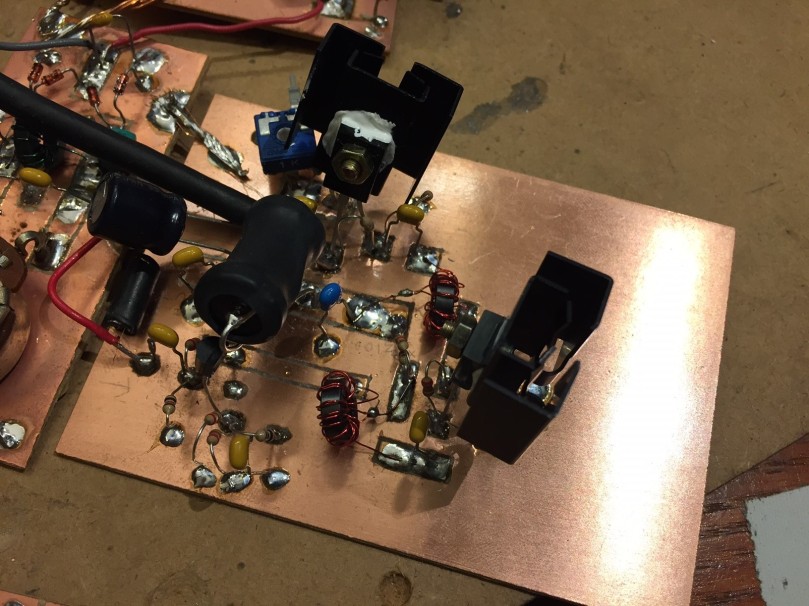
The module assembly and testing went fairly smoothly – using a variable-voltage power supply, it’s easy to vary the output power of the amplifier, and to observe the changes in PA heating that this causes. You can see the two large screw-on heat sinks on the BD139’s in the following pictures, as well as the the large ferrite bead which feeds the Final. There’s also a chunky 100uF cap at the DC input to the board for additional decoupling.

IMG_2288.JPG
The assembled Beach40 PA.


The problem I’m having now is the same one that plagued me way back in my assembly of the Virgin Receiver, my first first homebrew receiver: this amplifier would really love to be an oscillator. With the PA voltage set at 12V, any time the signal imput is sufficiently strong, the PA will fall hard into oscillation, and won’t stop until the PA voltage is brought way down or cut. I’ve been experimenting with emitter degeneration for the final BD139 (the original schematic has the emitter directly grounded). That’s helped, but not much. I’ve also changed the RF-carrying wires from hookup wire to coax, to mitigate feedback through other modules. Another help, but so far, the oscillation problem is still there. The next step will be to move the modules themselves around, to limit the amount that the high-power RF coming from the PA has to pass by earlier stages of the transmit chain (VFO, mic amp, balanced modulator) to try to eliminate feedback that way. Fingers crossed!


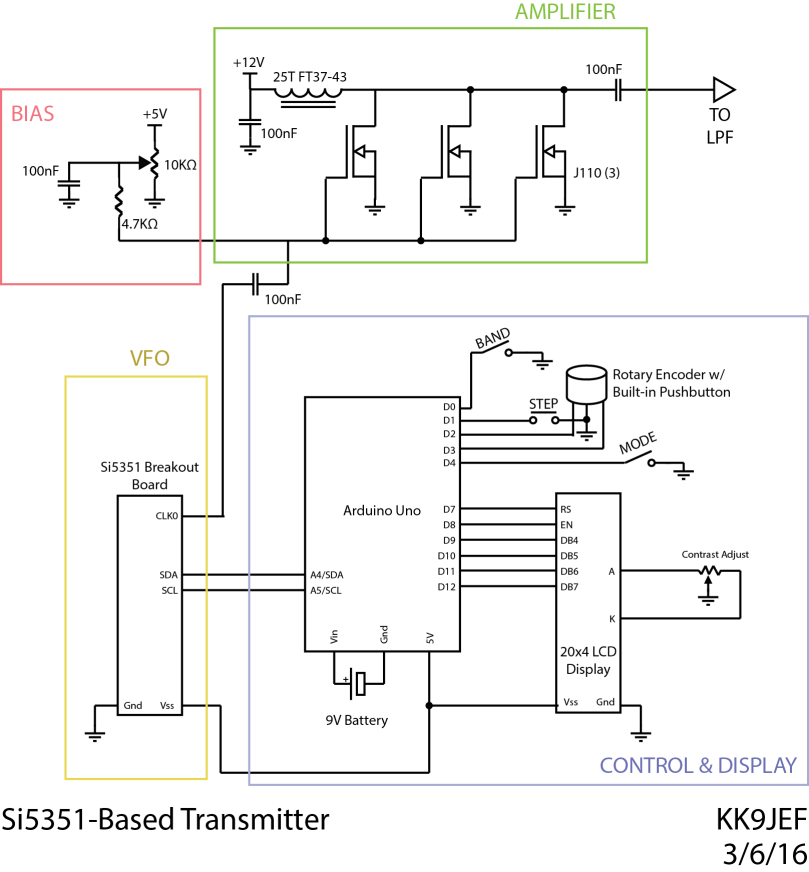
Next on the bench is a repackaging of an old project – my SI5351-based “VFO,” which for the better part of a year has been serving as my primary signal generator for experimental projects, spread out in all its Al-Fresco glory on a breadboard. With the amount of troubleshooting I’ve been going through on the Beach 40 project, I’ve decided to finally box up the SI5351, Arduino, and display into a proper project box, and make the thing a real SI5351-based Signal Generator. The schematic is essentially unchanged (minus the PA) since I used the project in my SI5351-based transmitter project, which is reproduced below:

CW Transmitter sCHEMATIC

To that end, I purchased an inexpensive nibbling tool and an expensive project box from the local Fry’s electronics, and have been working in the past couple weeks to marry the spread-out guts of the previous project with the clean lines of the enclosure. Biting out the large hole for the display 1/8″ at a time was time-consuming and strangely soothing.

At this point, the display and Arduino are connected, but I have yet to wire the two control buttons, rotary encoder, and Si5351 breakout board back into the Arduino. I also need a provision for getting the signal out the front of the darn thing, so I’m waiting on a shipment of SMA connectors and a jumper to go from the SI5351 breakout board to the front panel. So far, so good.

The code for this project is still on Github.


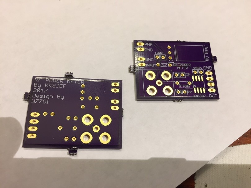
The last project on the bench is an RF power meter circuit, based on a circuit by W7ZOI from 2001. While the old scope-probe-across-a-50-ohm-load technique has proven very useful, I’ve found myself wanting a way to more reliably measure RF power at low levels, and to do it in a way that could be interfaced to a microcontroller or computer. To that end, I plan on using the W7ZOI circuit connected to an Arduino, much like Vu2ESE’s Sweeperino, to make digital power measurements.

IMG_2292.JPG

I rolled a little PCB for this project from OSHPark, and since that service provides PCBs in multiples of 3, I figure I’ll connect one board to an analog meter (for that old-school feel), one to an independent Arduino (for digital measurements), and embed one inside the SigGen project, for marrying signal generator and power measurement at specific frequencies. This last project, I figure, will be especially useful for examining filter behavior at HF and piping the information to a PC for display an analysis.


So that’s what’s on the bench at the end of March 2017. All of these will hopefully merit full posts in future as the projects come to fruition, but for now, the is the smorgasbord that is my bench.

Hear you on the air!

73