First Steps in Arduino-Driven DDS

Note: This project ulimately got packed up into the Si5351 Signal Generator/VFO.

With some of the gifties I received last week, I started to put together the beginnings of a DDS driven VFO using the Si5351 breakout board from Adafruit, controlled over i2c by an Arduino Duemilanove. (Credit where credit is due, this is heavily-based on m0xpd’s VFO, detailed over on his very fun Shack Nasties blog.)

The circuit, breadboard'ed and functional, outputting into the 'scope.
The circuit, breadboard’ed and functional, outputting into the ‘scope.

The wiring is fairly simple, between the Arduino, the Si5351 Breakout, and the LCD screen. Here’s the breakdown:

  • Arduino
    • Pin 1: Reserved for future encoder
    • Pin 2: Reserved for future encoder
    • Pin 3: Reserved for future encoder
    • Pin 4: ‘Up’ button (internal pullup enabled)
    • Pin 5: ‘Down’ button (internal pullup enabled)
    • Pin 6: ‘Up’ button (internal pullup enabled)
    • Pin 7: LCD Screen RS Connection
    • Pin 8: LCD Screen EN Connection
    • Pin 9: LCD Screen DB4 Connection
    • Pin 10: LCD Screen DB5 Connection
    • Pin 11: LCD Screen DB6 Connection
    • Pin 12: LCD Screen DB7 Connection
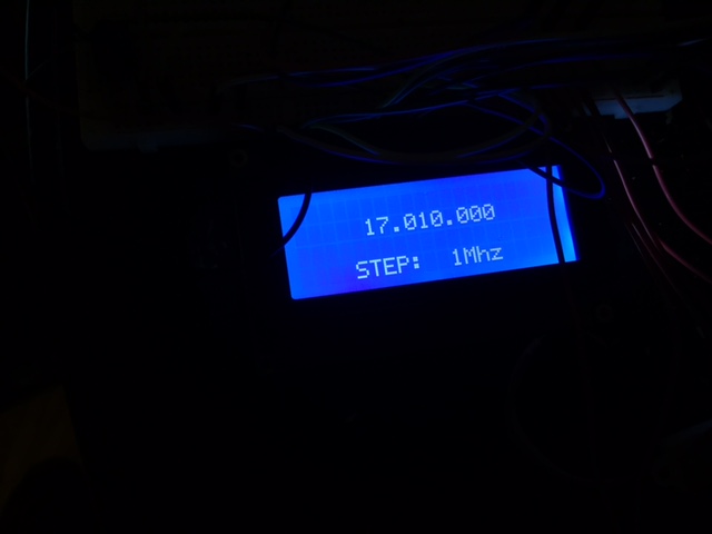
The 20x4 LCD screen is just for displaying the chosen frequency and step size, at this point.
The 20×4 LCD screen is just for displaying the chosen frequency and step size, at this point.

Here’s a very quick and dirty schematic of the circuit. The antenna symbol is meant to represent the output of the DDS.

Preliminary Schematic of the DDS VFO driven by an Arudino.

The full code driving this version is on Github. I’ll dive into this code and some more explanation as the project develops, but I thought it would be worth getting out there for now:

Santa in September

Santa (UPS) delivered some goodies today! Here’s what was in the mail sack:

Goodies from Ebay & Adafruit
Lots of toys on the desk! All nicely package and bubble wrapped.
  • From Adafruit
  • From KC9ON (3rd Planet Solar)
    • A six-pack of useful 40m Crystals – 7.030, 7.050, 7.055, 7.110, 7.114, and 7.122. A piece of cake to order through ebay, and John shipped them out in no time. Came packaged in a nice mailing envelop with invoice – would gladly order from this source again.

73

Si5351 DDS

Update: for more information on the evolution of this project, see First Steps in Arduino Driven DDS and Si5351-Driven Transmitter.

I’ve ordered a breakout board for Silicon Labs DDS chip, the Si5351, as a starting point for working with signals and forming a homebrew VFO. I think the first thing I’d like to try is putting together a “Polyakov-Style” direct-conversion receiver using KE3IJ’s excellent descriptions, probably for the 40m band, as a place to start. I’ve already got the bulk of the parts in my junk-bin, and a couple toroids are on their way

The folks at Etherkit have put together a very full featured library for the Si5351; I just wish it wasn’t so big! It eats up about 3/4 of the space on an Atmega328 by itself, which doesn’t leave a whole lot of room for other programming. Maybe it’ll be worth me implementing i2c of the Si5351 directly, since I don’t think I’ll be using a lot of the features of the Si5351 Etherkit library to start with.

Hello World, and a Scope

Hello World!

After digging my radios out of storage after about 10 years offline, I figured it would be worth documenting some of my activities online.

As far as radios, my equipment list includes:

  • 1 @ Baofeng UV-5R HT (2m/70cm, 4W Max), and CHIRP programming cable for same.
  • 1 @ VX-150 HT (2m, 5W max) w/o rubber ducky
  • 1 Icom T90-A Tribander HT… somewhere…
  • 1 Nagoya 2m/70cm mag-mount Antenna

As a theatrical electrician in my regular life, I’ve got a fair access to electronics gear (solding station, multimeters, wirestrippers and wire of various varieties), but today I picked up a nice piece of radio-specific gear – my first oscilloscope! It’s a used B&K Precision 1535a, rated for up to 35Mhz and 300V RMS.

BK 1535-a
Used BK1535-a, picked up for $40 on Craigslist. Some stray capacitance issues with that “square wave,” perhaps?

It’s been a little hard to find information on the history of the scope, particularly because B&K don’t list it on their manuals downloads page. Thankfully, Elektrotanya has a copy.

I think this thing will need a little calibration – its built-in 1Khz, 0.1Vp-p port is reading at a little less than 1.1 khz, but that could also be an issue with the calibration signal. More troublingly, it’s absolutely murdering square-wave inputs – you can see one pictured at right – making them look like some fine surfing waves. Not sure what I’m going to do about that, but I’m ordering a new set of probes anyway… we’ll see if that helps.

73