
So much has happened radio-wise in the past two weeks, and I’ve been quite delinquent in updating the blog. This post won’t even get to Field Day, nor my new transceiver, but I’ve got to start somewhere. So let’s get to it!
Using the MFJ-207 antenna analyzer I picked up at the SMCC Hamfest a couple weeks ago, I’ve now set up tuned, worked with, and taken down a 40m inverted-V four or five times now. Since space around my apartment is limited, I’ve been walking the 15 minutes out to the shores of Lake Michigan. The lakefront has ample trees and open space to erect an antenna without being too much in anyone’s way.
The first day I set up the inverted V was the most exciting, and went something like this. I took my dipole-kit out to the lake, which contains 200′ of thin nylon rope, a dipole center, a couple equal lengths of 18-guage speaker wire (35-ish feet each), two weights filled with rice to throw into trees, and three 8″ pegboard hooks. (The hooks make excellent ground-spikes to tie off the ends of the nylon rope. I picked up a bunch at Menards when they were on sale for 20 cents each.)

In addition to the antenna parts, I’ve been taking along a small SLA battery and powerpole adapter, a 25′ bit of RG-58 Coax, a homemade “ugly balun” (see below), the MFJ antenna tuner, a radio, headphones, a pad of paper and a pen. The heaviest parts of the pack by far are the SLA battery and the the two coax items. I’ve also sometimes brought a portable camp chair so I don’t have to sit on damp grass… but lying in the grass in the summertime isn’t bad either.

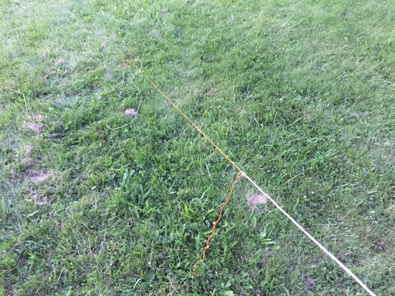
The process of putting up the antenna is straightforward. I unpack the kit and lay out the parts under a suitable tree. I throw one of the weights with a rope as high over a branch as I can, then tie the dipole center to the loose end of that rope. I lay out the two antenna wires roughly on either side of the center, and attach both wires, the ugly balun, and the coax to the dipole center. Once everything’s attached, I haul on the rope to raise the dipole center up as high as it will go, and tie the working end of the rope around a stake just under the center of the antenna. I walk the wires out as far as they’ll go (each now has maybe 5′ of nylon rope attached to the end), and tie them to stakes as well. The whole process takes between 10 and 15 minutes and is getting faster every time.
The first time I put up the inverted V was enlightening, to say the least. I attached the ends of the antenna wires directly to the ground stakes, and hooked up the MFJ tuner to the other end of the coax. The MFJ207 is essentially just a wideband oscillator with a 50-ohm output, with a built-in SWR meter. You tune across the frequencies of interest (in five separate ranges, see the MFJ 207 Manual for technical details) and read off the SWR on the analog meter. In this case, I was hoping to see a nice dip around 7MHz. Though that’s what the picture below shows, it was quite a process getting there.
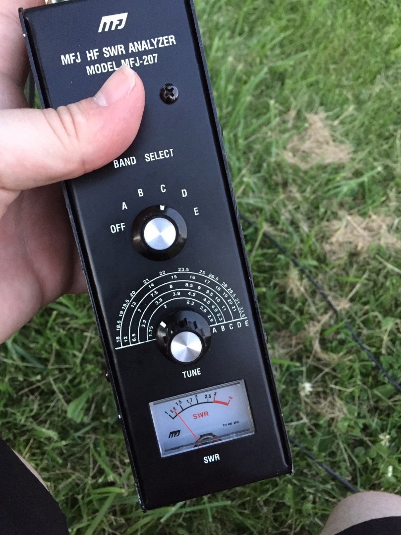
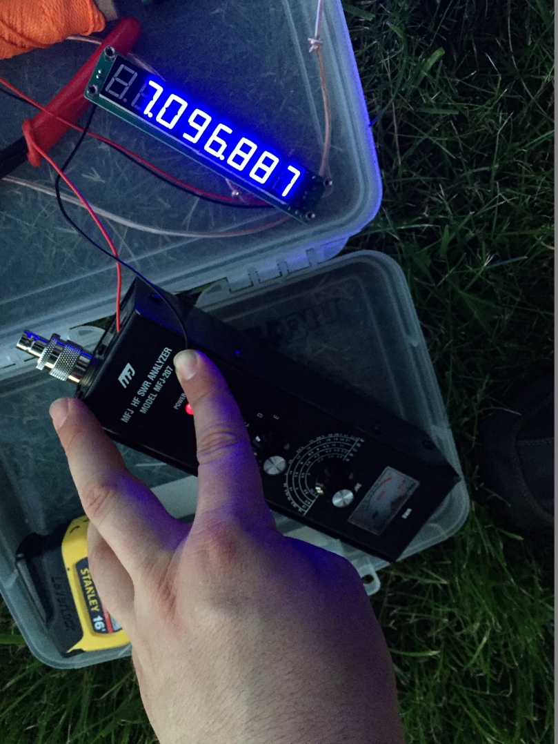
The first time I put put the antenna, it showed a clear dip… but a little under 5 MHz! To be sure this wasn’t just an issue with the calibration of the analyzer, I plugged my cheapie Ebay 8-Digit Frequency Counter (“Cymometer”) into the frequency-measurement port on the top of the analyzer. It read 4.87MHz. Dang. My antenna was definitely too long.
As a starting estimate of how much to trim the antenna, I did a quite back-of-the-envelope calculation of how “electrically long” it currently was. Taking the speed of light to be roughly 3 x 10⁸ m/s and dividing by our resonant frequency of 4.87 MHz gives a wavelength of 61.6 meters, which means each quarter-wavelength wire of the dipole is about 15.4 meters long. To work on the 40m ham band (7.0 to 7.3 MHz here in the states), let’s say the antenna wants to be resonant around 7.1MHz. Similar math to the above gives a wavelength of 42.2 meters (surprise!), or about 10.5m per wire. By this math, the wires were about 5m too long.
However, there are many factors that can cause an antenna’s resonant frequency to be lower than it would be in free space, and one of them is proximity to the ground. Not only was the antenna’s center only 6-7 meters feet above ground, but the ends of the antenna were literally touching the ground. Given these factors (and the fact that while I had cut the wires longer than necessary, I didn’t think they were that much longe), I decided to be conservative in the my trimming. What’s more, I left the ground stakes where they were, and replaced the trimmed sections of wire with nylon rope. In other words, the angle of the inverted V didn’t change as I trimmed the wires, only the length of the wires themselves, and therefore the height of the ends above ground.
With an eye toward being conservative with my trimming, and knowing that the math would have me trim 5 meters off the antenna in free space, I instead opted to trim 5 feet off each wire instead. This left each end of the antenna about 2′ off the ground, instead of touching it. After this brief surgery and re-attaching the nylon rope, the MFJ meter proclaimed the antenna resonant at 6.46 MHz. Now that’s better!
Another quick snip of 18″ on each end got the antenna resonant around 6.75 MHz, and another 15″ off yielded resonance at 7.097 MHz. For these measurements, I tuned the analyzer for lowest SWR, then measured the frequency with the frequency counter. In future, it seems like the dial measurements will be good enough for daily use, but for dialing in the antenna the first time, the frequency counter was very helpful.
To get an idea of the useful bandwidth of the antenna, I also swept the frequency up and down around the resonant point and took some frequency measurements. The antenna had better than 2:1 SWR between 6.922MHZ and 7.282 MHz. Pretty much all of the the 40m band, and certainly the CW portion that I plan to most immediately be working.
All in all, I consider the several outings this week to be great successes. The MFJ is surely worth the $15 I paid for it. I was battling some dodgy coax the first couple times out, which made it hard to take SWR readings without the needle jumping all over the place. A little Amazon order of some RG-58 fixed that. Now, I’ve got a working, tuned, successful antenna.
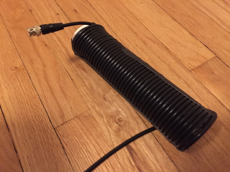
One more thought: the so-called “ugly-balun” or air-core choke. Mine is simply 25′ of RG-58 close-wound on 10″ of 1.5″ PVC pipe, secured with zip-ties and duct-tape.
My understanding of its usefulness is still rough (and there is much information, data, and heated discussion about it), but here’s what I think I know:
When using a dipole without a proper center balun (that is, an actual transformer that forces equal and balanced voltages on the balanced side from a single voltage on the unbalanced side), the dipole essentially becomes a “tripole”, with the outside of the coax shield possibly becoming part of the antenna and carrying RF. I say possibly, because it will vary with the length of coax between the transmitter and antenna feedpoint. This is undesirable, because we’d like the antenna itself to be the radiating/receiving part of the system, and not be depending on the physical arrangement/length of the coax itself.
One solution would be to install a proper balun (sometimes called a voltage balun) at the center of the dipole. This forces the voltages to each leg of the dipole to be equal, thereby eliminating common-mode current on the outside of the coax. However, a choke can also reduce current on the outside of the coax. For this reason, the coke is sometimes called “current balun” or “choke balun,” though strictly speaking it isn’t a balun at all.
Here’s a quote from one of the links above:
A choke is not a balun in any way. It’s given that description, ‘balun’, because it can do something a balun can also do, get rid of unwanted currents (CMCs) on the outside of the coax feed line. It can’t transform from a balanced to unbalanced state.
– ‘Doc
There’s lots of other useful information in that same thread, which I find myself returning too and musing over. It seems, long term, that a ferite balun is really the way to go for choking off stray RF, but in the meantime, adding the air-choke to the antenna feedpoint does seem to help somewhat. I’ll continue throwing it in my pack and experimenting in the meantime.
Hear you on the air!
73


