Up to this point, if I wanted to get on the air, I had three antenna options:
Walk 20 minutes to the lake, spend 15 minutes getting a 40m inverted-V set up in a tree, and hope I didn’t forget anything. This has been netting me good results, but is a bit cumbersome.
Set up the PHF40 loaded-dipole antenna on a tripod in the backyard. Also a bit cumbersome, and I’ve not had any success making a contact on that antenna yet. I suspect the efficiency is quite a bit down from a full size antenna.
Try the random-wire I’ve got strung up around the office.
While it certainly doesn’t feel like it in the August heat, winter is surely coming. In order to ensure I won’t have a long operating hiatus once the snow hits and going outside is impossible, this week I set about putting up a 40m dipole in an inconspicuous place.
I won’t share exactly where the antenna is mounted, but suffice to say all parts of the antenna are about 12ft off the ground – much more of a skywarmer than a DX antenna, I should think. I tuned this antenna the same way I did with my inverted-V, using just the MFJ-207 and a pair of snips.The antenna ended up being 31’6″ along each leg.
The final antenna is resonant around 7.075 Mhz with an SWR of 1.2:1 at that frequency, with a 2:1 SWR bandwidth of 6.9-7.240 Mhz.
Currently, the feedline is just a piece of RG-58 sneaking in through a window into the apartment. Interestingly, the SWR at resonance shoots up to 2:1 if I bring the metal window-frame down to within about an inch of it. I should note that I’m not using a balun with this dipole, just the usual center-conductor-to-one-wire, shield-to-the-other setup, so it doesn’t surprise me that the coax is coupling to the window. I’ll need to set up some kind of non-metallic passthrough to block airflow with maintaining the antenna characteristics.
After a couple evenings of listening, all signs point to this being a workable antenna! The map below shows the stations that I’ve heard (not contacted) in the past couple evenings. The station in red is one that I was able to contact, but we were fighting QSB and couldn’t really complete the QSO.
Moving on to the transmit-only portions of the Beach 40, today I completed the microphone amplifier. Powered on transmit only, it’s responsible for both boosting the microphone input level to inject it into the mixer, and for switching the microphone out of the circuit on receive, as necessary.
One difference that I’m going to introduce into the original VK3YE design is that I’m going to use a dynamic mic instead of an electret mic, specifically one of the mics I picked up at the SMCC Hamfest back in June. This likely means I’ll need a bit more gain in the pre-amp than if I was using an electret element.
Peter mentions the possibility of using a dynamic microphone on his page on the Beach 40. He says:
“The circuit is suitable for an electret microphone. If using a dynamic unit leave out the 22k [bias] resistor and possibly raise the 100n [mic] coupling capacitor value if insufficient or thin audio.”
Leaving the bias resistor out of the original circuit, and replacing a couple of the electrolytic caps with ones from my stock, I ended up with this:
A quick spice simulation shows about 15 dB of gain through the audio spectrum with a slight high-pass characteristic. Note that I’m making a couple of approximations here. I don’t know exactly what the impedance of the dynamic mic is, but varying its input impedance between 100 and 500 ohms shows only a 2dB variation in gain, so I’m not too concerned. Similarly, I’m measuring power into a 50-ohm resistor as a representative of the mixer, instead of modeling the mixer directly.
This circuit came together very quickly on a piece of copper-clad, just five pads and a few minutes of soldering. The next step will be attaching the mic amp to the mixer and determining whether I do in fact need more gain. I’ll also need to experiment with the microphone input cap to see if I need more low-end response from the mic. But this is a start!
Next on the bench is the low-pass filter, which is mostly responsible for curtailing the harmonics generated by the VFO and mixer. Since limiting out-of-band signals and noise is also useful on receive, the LPF is connected directly to the antenna socket to be useful in both modes.
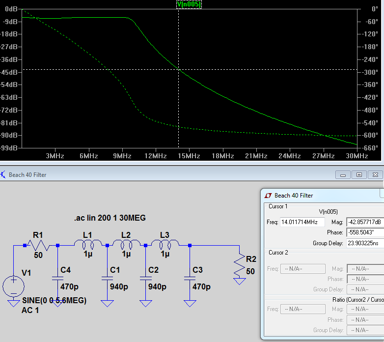
This LPF is particularly simple, using just three RF chokes and six capacitors. VK3YE’s original low pass filter used a couple components I didn’t have (namely the 820pF caps), so I played around a little in LTSpice to work out a viable filter with the components I had. Here’s what I ended up with:
SPICE simulations show that this filter maintains a similar low-pass characteristic to the original VK3YE design. Moreover, the insertion loss is approximately equal. The match to 50-ohms isn’t great, but is acceptable. And perhaps most importantly, attenuation at the second harmonic is strong at about 42dB:
Constructing the LPF was simple – just six capacitors and three molded chokes that I picked up on a recent trip to California. I laid the filter out on a small piece of scrap copper clad. I enjoy when the layout of a board can highlight the symmetry of circuit itself.
Before attaching the filter to the rest of the project modules, I did a quick manual sweep of it with my SI5351 board. It’s somehow very satisfying to roll the frequency up past the filter knee and see the higher frequencies just drop off. One word of caution – the SI5351 doesn’t have perfectly uniform output power across all frequencies, so I put one channel of the scope on the input of the filter and one on the output, to observe relative attenuation. Of course, terminating the filter is a must.
Filter attenuation at 14 MHz, roughly the second harmonic of the desired transmit frequency.
Today I tackled the audio amp section of the Beach 40. And when I say tackled, I think perhaps the player was already down, and I just had to fall on top of him.
The audio amp configuration I’m currently using is the bog-standard, straight-from-the-datasheet LM386 20x or 200x configuration. A SPST switch puts the 10uF cap between pins 1 and 8 of the IC, or takes it out of the circuit.Currently, I don’t even have a volume control pot in place. Peter VK3YE later modified the LM386 configuration for greater gain and less hiss, which is something I’d like to tackle once I’ve gotten the rig working.
Part of what made today so simple is that I’d already built this audio amp section for another project. I’d been using a bit of scrap copper-clad to experiment with coupling between an NE602 and an LM386, to see if passive filtering would be a useful option for future receivers without introducing too much loss. But since I haven’t touched that project in a couple months and this one’s exciting me now, that board hit the chopping block.
The old receiver experimentation board. What a Frankenstein!
Extracting just the audio portion of the board was simple enough – now that I’m looking at the pictures and seeing the two big bypass capacitors on the red power line reminds me that I need to think about bypassing the power input at the source, probably with something beefy. I’ve had enough LM386’s turning into oscillators, and I’d rather not subject my ears to that too much if I can avoid it.
With the VFO, mixer, and audio amp “completed,” I now have the bare bones of the receiver portion complete. Of course, there’s exactly zero filtering, either at the front or the audio portion, so it’s not like this would make a particularly reliable bit of kit. But it’s got enough parts that I can string them together and test.
While I didn’t exactly succeed in keeping the leads short, using clip leads was just the fastest and simplest way to tie the modules together. RF from the ‘antenna’ (read: long bit of wire strung around the office) is brought into the mixer via the white clip lead at center. The VFO drives the mixer and converts the RF down to audio, where it’s amplified and sent out to the headphones.
To generate a test signal, I used my SI5351-board without an amplifier, with just a short bit of wire hooked directly to the output of the Si5351. I set the output somewhere around 7.150 MHz. Tuning the VFO across the band with the polyvaricon, I found my strong local source no problem. The receiver works!
I can see why Peter later added a fine tuning control to this project – with half a turn of the variable cap, I’m covering around 200Khz of the band, which makes tuning in to an individual station tricky. I do have a rather large panel knob in mind for the cap, which will help, but we’ll see if it’s enough. If I can’t get the VFO drift a little more under control, that fine tuning cap might be necessary to help stay on frequency.
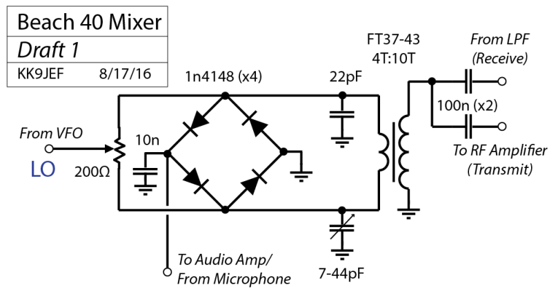
Charging forward with my project to build VK3YE’s ‘Beach 40’ 40m DSB transceiver, today I tackled the diode ring mixer. The mixer serves as the product detector, converting RF signals down to audio. It also serves as the balanced modulator, turning audio from the microphone into a double-sideband signal at the appropriate frequency.
This is a particularly simple diode ring arrangement, with only one output transformer to wind. No trifilar windings here:
The local oscillator signal is provided by the VFO I built, which has an available power of at least +7 dBm, as required for good linearity in a diode ring. In receive mode, HF signals from the antenna get converted down to baseband (audio) and pass out the audio port. In transmit mode, the signal flow is reverse, and signal from the microphone travels in through the audio port and modulates the local-oscillator, creating a double-sideband suppressed-carrier HF signal, which is then routed to an RF amplifier stage before ending up back at the antenna.
Two balance controls are provided for nulling out the carrier at the RF port – a 200-Ohm trimpot (which also serves as the LO injection point) and a ~40pF trimcap, which balances the nominally 22pF cap on the either side of the ring. No attempt was made to match the 4 diodes, they were just the first four 1n4148s I pulled from the bag.
The following picture pretty well illustrates my process of building one of these little modules. First, I re-draw the schematic by hand, just to make sure I’ve got a handle on it. Then, I’ll identify the different networks of attachment within the circuit, as each one of these will want to be its own isolated pad. I use that to make a rough sketch of the pad layout (bottom-left in this picture). Much erasing and re-doing happens at this stage! Once that’s mostly sorted, I’ll do a more precise sketch of the pad layout using the actual component sizes (bottom right). Then I’ll duplicate that design in pencil on the copper clad, and have at it with the Dremel, followed by the soldering iron.
The completed diode-ring mixer. The RF comes in/out of the yellow 100nF cap on the left. Audio comes in/out of the rectangular pad at the top center. The LO is injected at the center pin of the balance pot. Coupling capacitors got moved to other boards.
This balance pot, by the way, came out of the mysterious silver radio I got at the DeKalb Hamfest back in May. Huzzah for re-using old parts!
Upon testing, I’m encountering a bit of difficulty totally balancing this mixer. From my understanding of how the diode ring works, with no signals present at the audio port, there should (ideally) be nothing appearing at the RF output port port. I was expecting to see a little feedthrough of the LO, but the lowest I can seem to acheive by tweaking both the balance pot and the trimmer capacitor still leaves about 50 mV P-P of LO signal at the RF port, which seems like a bit much. Then again, the LO signal is at around 4V P-P going into the mixer, so proportionally, that’s not too shabby. (not quite 40 dB). Some of that could also just be radiating straight from the LO, or from the 12″ clip-lead connecting the VFO and the mixer at this point.
The mixer/VFO test setup
For the time being, I’m going to note the balance issue and move on. From my reading, I understand the proper termination of the mixer is essential for good balance. Since the surrounding components are not in place yet, I can’t imagine I have proper termination on this thing. I’ll return to this down the road as the transceiver takes shape.
After listening some of of the recent episodes of the Soldersmoke podcast, and hearing about their adventures great and small having to do with VU2ESE’s BITX SSB transceiver, I’ve got a hankering to build something from scratch. Rather than jump in at the deep end, as it were, with an SSB transceiver, I’m starting with something more approachable: Peter Parker VK3YE’s “Beach 40” Double Sideband transceiver.
There’s a host of information on the internet about this project, but Peter’s project page, linked above, is a good place to start. You can also find some expanded notes on the build in a write-up of the Beach 40 Lo-Key magazine at the time, several years back.
The project is conceptually simple: A balanced diode ring mixer functions as the product detector on receive, and as the balanced modulator on transmit. Hook up the RF-pre-amp and an LM-386 audio amp, it’s a receiver. Hook up a mic amplifier and an RF power chain, it’s a transmitter. No muss no fuss. A handful of transistors, one IC, about 2-3W RF output.
Peter’s original design used a ceramic resonator in the VXO, though later versions of his employed a “super-VXO,” in which two or more similar crystals are paralleled for extra pulling range. I decided to use a true LC VFO in mine, as I’d like to cover from 7.125 to 7.300, the entire USA SSB range, if I can.
This is VFO design I started with. It’s a Hartley oscillator straight out of EMRFD. To that, I added a simple common collector buffer stage:
Unfortunately, this design didn’t produce a high enough power level to drive a diode-ring mixer. Traditional diode ring mixers want to be driver with around +7dBm available power on their LO port, and I was only seeing 2 dBm. So I added an additional common emitter power stage to boost the signal level.
Once the thing was oscillating at the proper power level, I spent a good hour tweaking the inductors and capacitors in the oscillator’s tank circuit to get the frequency spread down to the appropriate range in the 40m band. The final result is actually a bit wider than I’d like it to be, so some additional tweaking in the future will be necessary. I also found that, as I added additional shunt capacitance to the tank, I had to increase the coupling capacitor (originally 47pF, now 220pF), to get the circuit to continue to oscillate reliably. Here’s what I finally ended up with:
One thing this process really drove home is the importance of shielding the VFO – the hand capacitance effects alone during debugging were making me a bit crazy. Sometimes just reaching in to hook up a scope probe would cause the thing to stop oscillating or start oscillating, or develop some parasitic oscillation…. woof. I’ll have to build a little box for the thing now that it’s essentially in the right shape. But for the moment, here it is, in all is little glory:
As I’ve documented before, I find that a variation on the Island Squares method of circuit construction is very approachable for this kind of circuit building. Essentially, small isolated pads are cut into a piece of copper-clad board using a dremel, and the components soldered to those. Ground connections attach to the ground plane of the board. It’s easy and quick, and allows for long connections to be made when necessary (the 12V bus on this project spans one whole side of the board, with de-coupling along the way).
I’m planning to build the next stages in the order Peter suggests in his Lo-Key article: Audio output amplifier, the diode-ring mixer, low-pass filter, mic amplifier, and the RF power chain. Since he originally published the design, Peter’s changed from a discrete-component to an LM386 audio amp, added an RF pre-amp, and stuck an L-Match tuner inside the case as well. I’m planning on adding the first two modifications, and perhaps an outboard unit for the third.
Last weekend, At the Hamfester’s Hamfest in Peotone, IL, I picked up a little Scout Regen kit from a fellow ham. The gentleman I bought it from was just lamenting to a friend “Nobody builds anything any more…,” but when I walked up to check out the un-built kit, he added, “….except this guy!”
It was unbuilt, but the metal frontpanel already had its decals applied (or perhaps pre-printed?), which was a nice place to start. I don’t have a great track record when it comes to applying decals and labels.
The un-built Scout Regen kit, sitting atop the variable power supply I also found in Peotone. Also included: a ganged variable capacitor for future experiments.
The overall build took about 2 hours. The Scout Regen Builder’s Manual from the QRPKits website is very thorough, and was easy to follow. The only issue I ran into was a missing 5pF cap for the detector section. I substituted two 10 pF NP0 caps from my stock, soldering them in series before installing them in the PCB. Additionally, after completing the first part of the detector section (basically, everything installed but the coil and the power switch) the current drain had jumped to 20 mA. After finishing the build, the current dropped back to under 10 mA. How odd.
The completed Regen receiver kit.
Listening with this kit is a lot of fun. Regen control is smooth, but very narrow; I may replace the regeneration control knob with a larger one. There’s all kinds of interesting things in the span of the receiver. Shortwave stations, the 80m and 40m hand bands, I found a couple different “WLO” beacons… really nifty. It’ll be nice to put on in the background while working on future projects.
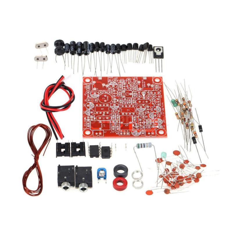
Back in March, QST magazine published an article about modding a cheap Forty-9er kit from eBay to incorporate a digital VFO. The original Forty-9er was a kit from the NorCal QRP club, a 40m transceiver designed to run on a 9V battery, hence the name. It, like many other kits, is based around an NE602 and an LM386. In the last couple years, cheap kits bearing the same name have been appearing on eBay, which bear only a scant resemblance to the original. The biggest difference is that where the original kit had a VXO attached to the NE602 mixer, the eBay kits are designed to be rock-bound to a single frequency. Perhaps this was the motivator for the QST article, to restore some frequency coverage to these fixed-frequency kits.
The Forty-9er kits from eBay – not a huge number of parts, but not a tiny kit either.
The process of using a digital VFO with an NE602 architecture is simple enough. Specifically, an AD9850 breakout boardis used to provide the signal, and a small BJT amplifier increases the power output from the DDS chip. The oscillator power is adjusted to show about 300mV P-P in-situ. After the article was published, one of the authors, K2ZIA produced a limited run of kit boards, which include the amplifier and sockets for both the AD9850 board and an Arduino Nano to control the DDS over i2c.
The K2ZIA kit board, with attached Arduino Nano and AD9850 board. Image credit: K2ZIA
I purchased the breakout board, AD9850, Forty-9er kit, Arduino Nano, and a rotary encoder from a fellow ham, Justin AJ2Q, who had gathered the pieces but was focusing on other pursuits and wanted to pass the project on. Final assembly was pretty straightforward; there are a couple of mods that need to be made to the Forty-9er (specifically, replacing the oscillator crystal with an input for the VFO, and swapping the crystal input bandpass filter for a much-wider two-element bandpass filter), and connection made so that the Arduino can detect when the key is down and shift frequency. AJ2Q had already done most of this, so only some final tweaks and cleaning up some soldering were necessary.
The original Arduino code was designed to make use of a 16×2 LCD display to display the current frequency, as well as licensing information according to the 40m band plan. Since I’ve already been playing with an LCD display on another ongoing project, and since I wanted this to be a simple and durable bit of kit, I wrote a bit of code that instead flashes the current frequency in morse code on a panel-mounted LED. The display is triggered by the press of a button. The number of digits to display is configurable. I’ve found that just displaying the three kilohertz digits is plenty (I don’t need to be reminded I’m on the 7 MHz band every time, and I don’t need precision better than KHz for simple operating). As always, you can see the code on Github.
The internals of the transceiver. The two green perf-boards are an experimental audio filter to be documented later. The 40-9er board is bottom-left, the K2ZIA board is bottom right, and the small black board on the upper right is the rotary encoder mounted to the front panel.
The full schematic of the original Forty-9er as well as the necessary mods can be found on Farruk K2ZIA’s website. The only additional hardware changes I made were to wire an LED and a 1k resistor between Arduino pin 14 and ground for the LED, and an SPST button between Arduino pin 4 and ground to trigger the frequency display. Like the original code, depressing the encoder changes the tuning rate, though I modified the possible step values to be only 1000Hz, 100Hz, and 10Hz, in that order. 1KHz is useful for zooming around the band, 100 Hz is useful for tuning a specific signal, and the 10Hz step is mostly for resolving SSB/DSB/AM signals cleanly.
On the rear of the radio are the BNC antenna jack and the power pole power input. (Useful tidbit – a pair of connected 30A powerpoles fit neatly in the cut-out for a VGA connector!) I’ve yet to fashion a front-panel, so the connections on the Forty-9er board for a key and headphones are directly accessible.
I’ve had the rig out to the park a handful of times now, and it sounds good! Like my other direct-conversion NE602-LM386 experiments, the audio quality is great, but broad as barge, so selectivity suffers. The sidetone is clean, at around 700Hz, from the Forty-9er’s little BJT oscillator. I enjoy being able to tune up into the phone portion of the band and listen to SSB QSOs and nets and such, which provide a good sketch of current propagation conditions. Being able to quickly switch between tuning steps is helpful, as I tune around and try to find someone sending CW slow enough for me to keep up.
The top of the rig. Not fancy, but functional.
The only major limitation of the rig is that, with only a single-resonator input bandpass filter, out-of-band signals can get into the radio and cause interference. Specifically, World Harvest Radio WHRI, who maintain and 500KW (no that’s not a typo) transmitter in South Carolina, is often audible everywhere on the dial, which is distracting at best. A stiffer bandpass filter will be necessary soon. I’ve also been experimenting with a peaked audio filter to help with reception of CW, but that’s still experimental.
The unit puts out about 3 Watts, which proved to be enough to make my first CW contact and, over the weekend, my second. The gentleman on the other end this time was Gary N4PIR, who was running 5W on his FT-817 into a trapped vertical. I think a little afterburner would be helpful on my end, as we were definitely fighting QSB. But that’s a later project.
I’ve just returned from a trip to California, and as usual, I took the opportunity to stock up on electronic parts. There are several suppliers and both new and surplus electronic components in Silicon Valley – their prices aren’t universally better than what you’d find online these days (though they shine in some categories), but they do have some advantages. You can buy just one of a component if you like, and you never know what you’ll stumble across. This trip, I made the full sweep of stores in the south bay: Halted, Weird Stuff Warehouse, Anchor Electronics, and a trip to Fry’s as well. Sadly, Advanced Component Electronics (ACE) seems to be permanently closed.
This trip, I mostly picked up small components, with a focus on inductors and ferrite beads, in a variety of standard values. I have in mind bandpass input filters for the new transceiver and VFO circuits for future projects. Particularly fruitful was a trip to Excess Solutions, where everything was half off. While this makes me concerned about their future, it was a particularly bountiful shopping trip.
I also grabbed a weird box with thermistor markings on the back. I haven’t opened it up to see what it is yet, but the box with three nice 10-position switches seems like a handy thing.
And lastly, a small collapsible antenna with an N connector. Fun!
I should also drop in here, since I haven’t in awhile: if this blog ends up being useful to you or you’re building something similar, I’d love to hear from you! You can drop me a line at kk9jef [at] gmail.com