tl;dr: My build of KE3IJ’s DC-80 Receiver for 40m works! Building radios is fun!
I stumbled across KE3IJ’s version of an RA3AAE-style (V. Polyakov) receiver some months ago as I started looking into homebrewing my own receiver/transceiver. I figured a direct conversion receiver would be a good place to start, as it would give me immediate reception with a simple pre-selector filter, mixer, and audio amplifier. RF filter designer, and IF filter design in particular, scares me a bit as a new radio builder, so I figured a superhet was probably a little too advanced to start with. So when I stumbled across KE3IJ’s version of a direct conversion receiver that seems to have reduced some of the issues with direct conversion receivers (microphones, AC or ‘common mode’ hum), it seemed like a reasonable place to start. You should absolutely read his full write-up on his build.
Here’s KE3IJ’s original design:

The central, exciting part of the DC-80 is that the VFO is tuned to half the operating frequency. That is, to tune in a signal at 7.040 MHz, you would set up the VFO to oscillate at 3.520 Mhz. Which explains why the original design lists the VFO range as 1.79-2.0 MHz for reception on 80 meters.
Rick has some interesting theories (and has done some experimentation) as to why the half-frequency VFO works that are well worth reading. After trying some different mixer options and settling on the two pairs of anti-parallel diodes, he concludes that what’s actually happening has little to do with “frequency doubling” or somesuch. Rather, an incoming signal (at, say, 7.0 MHz) mixes with a half-frequency VFO (in this case, at 3.5 MHz) to produce two signals at 7+3.5 = 10 MHz and 7-3.5 = 3.5 MHz. This copy of the original signal at half the frequency (3.5 Mhz) then mixes again with the half-frequency VFO (3.5 Mhz) to produce a baseband signal (“0 Hz”).
Seems like a plausible mechanism to me… and regardless (spoilers), it works!
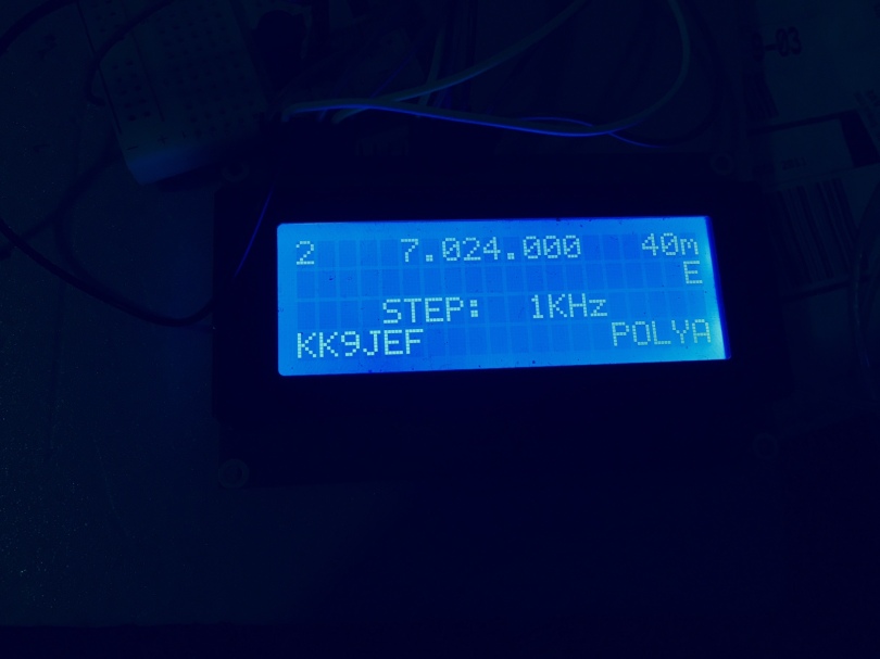
One change I made was to replace Rick’s “quick and dirty” VFO (since I don’t have an AM radio to tear apart at the moment) with the Si5351 derived VFO I previously built. I’ve upgraded the Arduino code (available on Github) with a band-select button to jump between the various HF bands, and a mode button to change between some operating modes. For this project, I mostly left it in “Polyakov” mode, which just means the DDS VFO is outputing half of the frequency displayed on the screen.

Sidebar: I added a few additional features which I was updating the Arduino code. When you press the Band Select button, if you’re within one of the HF bands, the Arduino will remember your current tuning and return to that frequency when you cycle back to that band. Also, the “E” in the upper corner of the above picture indicates that only Extra-class licensees may transmit at the displayed frequency: I baked license-permissions into the code as well. Being only a General, I wouldn’t be allowed to transmit here!
The other other change I made was to implement a 40m band pass filter instead of the original 80m filter. I just ripped the values straight out of Rick’s original suggested for a 40m bandpass. I really don’t quite understand it, but it does seem to isolate the 40m band nicely.
So, with those changes in place, the actual schematic became:

Which turned into the following pile of spaghetti on copper-clad and a breadboard:

With the solder cooling, I plugged a long bit of wire into the antenna input and set up my little 40m Pixie on the YL’s desk about 6′ away with a 7.114 MHz XTAL. I tuned the VFO to 7.114.500 and clicked the key on the Pixie, and…. Sound! A glorious 500 Hz tone! What a beautiful feeling, when something scratch built works. Flush with excitement, I hauled the receiver out to the backyard and plugged my ~1/4 wavelength bit of wire (10m) antenna, and boom, strong signals coming in from about 7.0 MHz to 7.060 MHz. The fact that this was during the ARRL November CW Sweepstakes meant that there were many signals on the air to listen to, many of them running 100s of Watts for contest’s sake.
Not bad for a first outing! Several issues exist, of course, in no particular order:
- Having the 9V battery biasing the audio pre-amp transistors does increase the signal volume in my earbuds by maybe 2-3 dB, but it also increases the background noise volume by maybe 10 dB! With that 9V no longer in the circuit, signals appear faint but audible, and noise drops almost to nothing. I haven’t gone back and confirmed that it’s not an assembly error, but this does not seem like the desired behavior.
- Sadly, the work lights in my office are very RF noisy. I have three 24″ fluorescent fixtures mounted above my desk, and when they’re on, the antenna and receiver both pick up ungodly noise.
- Something in either the VFO, the rotary encoder, or the backlit LCD display makes an awful THUMP in the audio whenever I change frequencies. More experimentation will be necessary to figure out where that’s coming from. Initial theories are the I2C lines controlling the display, or maybe they’re an artifact of the frequency change on the Si5351 itself.
- I suspect that driving the diode mixer directly from the output of the Si5351 breakout board may not be pushing the diodes into conducting for much of each cycle… Some kind of buffer may be necessary.
Hear you on the air!
73

[…] decided to build a receiver like this for the 40 meter band (around 7 MHz). He started with an earlier design and replaced its analog VFO with his Si5351 DDS […]
LikeLike
Well done, very interesting project, I built it too, mine was for 40m, I used it a cobra 25 cb transceiver which had defuncted pll circuit, I put it inside the cb on the receive side and hey presto received the full 40meter band width, I did not use DDS, I made a vco and it works very well, I have to sort out transmitter to cover the 40m too. Thanks for info.
LikeLike
I have built this reciver and it works great. This was my first reciever ever and it makes one very happy. Thank you KK9JEF for sharing this article. – 9V1PM/VU3WGE
LikeLike