This morning, I trekked out to the Hamfesters’ Hamfest in Peotone, IL for the second year in a row. Though the rain threatened to put a damper on the day, the sun had burned through by 10am and left everyone alone.
There was an interesting mix of vendors at this year’s Hamfesters – lots of assorted “hardware” (tool, dental picks, kitchen sink), but also a good number of radios new and old. There was a table absolutely stacked with older 2M gear, mostly Heathkit. A couple newer ICOM rigs, the usual FT-101e’s… nothing too exciting. I scooped up a handful of beefy heatsinks meant for CPU’s, but will be re-purposing them as LED heatsinks in future projects.
I did find two real scores at the Hamfest today. First, from Patrick-J, a secondhand, gov’t-surplus Tektronix TDS644a. It’s a 4-channel digitizing scope, with 500MHz bandwidth at 2GS/s, and I got it for a song.
Not unexpectedly, when I got it home and opened it up, it’s in need of a good re-cap-ing (see, for example, W6KWF’s recent video on this subject.) I’ve already got two packs of electrolytics on their way from the wide wide eBay, so I’ll pick this project back up on a future weekend.
The second find was a small, slant-top box with a 1mA DC meter movement already built into the top. It was configured originally to be a shunt ammeter, but I really just wanted the nice box and meter. Instead of measuring AC current, it’s now set up to measure RF power.
The original unmodified meter – something out of some other amateur’s homebrew shack.
The only external sign that the box has been altered is the presence of a small SMA jack, but the internals are entirely different. I populated and installed one of the AD8307-based power meter PCB’s that I cooked up back in March, fed directly from the external SMA connector. The output feeds the mA meter through an op-amp buffer – I started with a direct connection, but the AD8307, with its 10k-15K output impedance, wasn’t up to the task. The voltage output from the AD8307 is also directly fed to the red external binding post, for measurement with a DMM. I added a little green power LED to remind me to turn the darn thing off. I left the original switch in place, just because it feels right.
The final meter, with an SMA/BNC adapter hanging off it.
The schematic for this project is essentially the same as W7ZOI’s Power Meter published in QST – see that article for details, as well as Wes’ further errata. The meter covers the range of the AD8307’s output voltage, from about -70dBm to +20dBm. As I’ve been working on putting together my BITX homebuild (more on that soon!), I’ve been thinking that having an RF power meter with an analog movement would be very helpful in peaking filters and looking at relative input and output power. And now, I have one!
In contrast to my field day adventures last year, in which I hung out with the folks from the North Shore Radio Club and ran 100W on a K3S, this year I opted for a decided more small-scale approach. Using my ATS-4 receiver, I ran 3.5W CW on 15m, 20m, and 40m for about four hours Saturday afternoon in the lakefront park here in Chicago.
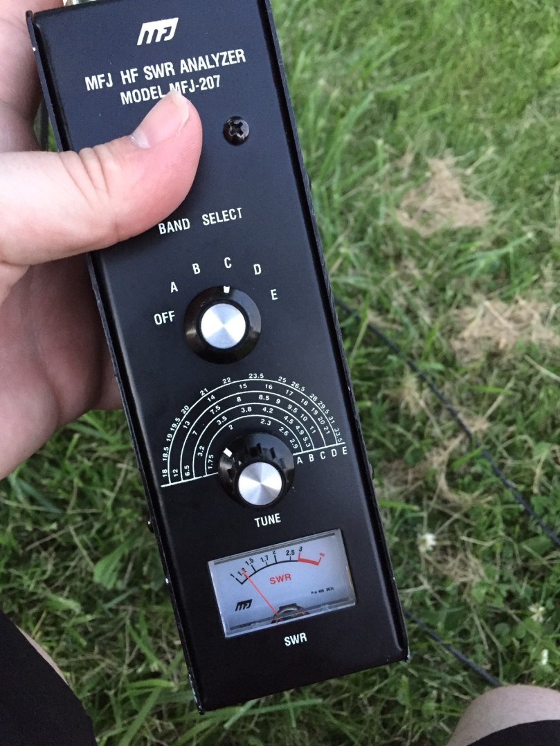
My antenna was a single 40-some-odd-foot wire hung from a tree, fed by my ZM-2 antenna tuner. I think when I built the ZM-2 last year, I goofed something up in the SWR circuitry – the built-in LED should go out at minimum SWR, but mine seems to be brightest at low SWR. To compensate for this, I brought along the MFJ-207 Antenna Analyzer I got at the SMCC Hamfest last year and used that to adjust the antenna tuner.
With the big analog, multi-octave dial on the front of the 207, I found it useful to first tuner the ATS to the desired frequency (say, 14.030) while attached to the antenna and adjust the analyzer until I heard the “WHOOP” of its signal generator in my headphones. With the frequency of the analyzer and receiver close to matching, I’d move the coax back from the tuner to the analyzer and adjust the ATU until the 207 showed lowest SWR. Reconnect the ATS, and away we go!
The MFJ-207 Antenna Analyzer covers up to an octave with a half-turn of the variable cap. Listening for its signal on a receiver made it much easier to find a specific frequency.
I used a new battery setup for this outing – a 12V, 6000mAh TalentCell lithium-ion pack that I borrowed from work. I love this pack – a little less than a pound, charges from a wall-wart, and has a built-in barrel connector and on-off switch. There are also models with a built-in 5V USB charging port, for topping off cell phones and other devices on the go. While the ATS is designed to run at 12V MAX (not 13.8V), I found that the 12.2V the pack was putting out proved to be fine – it seems the limitation is in the heat dissapation from the BS170 finals, and running relatively low duty-cycle search and pounce that wasn’t an issue. I’ll be ordering one for my own use soon. (Or perhaps the even more compact 3000mAh version – the size of a deck of cards!)
The rest of the pack list included:
A HamKey brand iambic paddle
A golfball and a kite-string winder for getting the antenna wire into a tree
A small battery-powered speaker with 1/8″ aux input
Variable DC and Coax jumpers
A notebook and pen
A folding camp chair.
All of the above fit into a small laptop bag, along with a few other tools and bits I didn’t end up needing.
The full field day setup, minus the antenna.
I managed 69 contacts, all QRP CW hunt-and-pounce, during my operating time – no tremendous DX, but I did hit a couple of rocky-mountain states and a plethora of sections up and down the East Coast. Final score was just over 1000 pts – that QRP multiplier really stacks up!
I also couldn’t have asked for better weather on the day – 72 degrees and slightly cloudy with a pleasant breeze. Simply stupendous.
As I alluded to in my March bench report, I’ve been working on packaging up my old SI5351 VFO that sat on a breadboard for two years into a functional signal generator for the bench. That project is now essentially complete, though there are a couple of planned improvements in the works.
The heart of this project is a Silicon Labs Si5351 clock-generator IC, on a little interface module from Adafruit. With an I2C interface, it can output square-wave signals at roughly 6dBm anywhere from 8Khz to 160 MHz. This nifty little chip has been around for a few years, and has been used in many a homebrew radio rig, including the work of N6QW, N2CQR, M0XPD, and other. Jason NT7S was essentially in building some of the earlier Arduino-friendly libraries for controlling the Si5351. With such a wide frequency range and the confidence that comes from XTAL-derived, PLL frequency generation, this little chip has breathed life into rigs both new and old.
With the hardest part of building a SigGen (actually producing the darn frequency) neatly packed away in silicon, what remains for a builder is to wrap the thing in packaging to promote ease of use and flexibility. That’s where the fun of this project lay. The parts list ended up like so:
The project box and the LCD display were the most expensive parts of this build by a wide margin, although both would be available for quite a bit less with a longer lead time from oversees.
The SigGen has 4 different software modes:
VFO – The primary output frequency matched the displayed frequency. Frequency steps are 10kHz, 1kHz, 100Hz, and 10Hz.
Test – Same as VFO, but steps are 10MHz, 5 MHz, 1 MHz, 500kHz, 100kHz, 10kHz, 1kHz, 100Hz, 10Hz, and 1Hz.
Polyakov – Primary output frequency is half of the displayed frequency, for experimenting with half-frequency-driven mixers. Step size is the same as VFO mode.
BFO – Adjusts the secondary output frequency, for using the SigGen to drive a Superhet directly. Steps are the same as in Test mode.
The SigGen’s three pushbuttons (one built into the rotary encoder and two next to the LCD screen) do essentially the same thing in each mode:
Encoder: Changes the frequency step size, per the step options above.
Mode: Changes through the software modes, per above.
Band: Advances to the next highest Amateur band frequency, to aid with band-changes especially in VFO mode. For example, if the current frequency is 5.72MHz, pressing the Band button sets the frequency to 7.0Mhz, the bottom of the 40m band.
There are still a couple improvements I’d like to make, namely replacing the cheapo detent-based rotary encoder with a nice smooth continuous one, which can be had for about $10 on eBay – using a detent-based encoder as a VFO is a pain in the patoot. I’d also like to implement a sweep functionality to sweep through various filters, but that would require a bit more UI work as well.
This gadget has been complete on my bench for a month of so, and has already been useful in working on my variable-bandwidth superhet… but that’s a story for another post.
Sunday morning I attended the Six Meter Club of Chicago’s annual hamfest in Wheton, IL. Much like my visit to them last year, it was a well attended, fairly well stocked event, with perhaps 4 or 5 dozen tables outside and the usual smattering of vendors indoors. I was a bit of a lazybird this morning and din’t get there till close to 9am, when the flea market folks were already making noises about packing up. Thankfully, most stuck around until after the 11am auction.
There were a number of tube testers at the fest today, both at the flea market and indoors. But the bell of the ball was an old Rocketest freestanding model that showed up at the auction. I think it went for $10 to a fellow who really just wanted the interesting nameplate. Sad to see it get parted out, but it really has reached the end of its time.
Speaking of the auction, that’s where I picked up most of my haul today. All in all, I can home with:
A Tenma 72-475 sweep generator (working!)
A ‘Model 175’ Oscillator Comparator (not yet tested)
From some old homebrewer’s box of bits at the auction, $1 each:
An inductive SWR bridge
A resistive SWR bridge with detector circuit and DC amplifer
Another SWR bridge, I think?
A 1/4″ headphone extender with volume adjustment
Five sheets of some thin, flexible copper clad for experimenting (a dollar a sheet!)
Another breadboard (can never have too many)
A spare set of flush cutters
I haven’t been able to find an available online manual for the 72-475 sweep generator (just this datasheet for a similar model) but it seems to be a relatively straightforward device. The main dial selects between 0.0 and ~2.3 continously, and 7 range switches select between 1Hz, 10Hz, 100Hz, 1KHz 10KHz, 100KHz, and 1MHz multiplies.
In manual mode, the device is simpler a function generator, with sine, sawtooth, and squarewave outputs. In swept mode, the device will sweep over about 3 decades below the selected range. So, for example, with the dial at “1.0” and the “1MHz” range selected, the automatic sweep will go from 1 Khz to 1 Mhz. It can sweep linearly over the range or logarithmic-ly, and total sweep time is adjustable from about 0.3 seconds to 15 seconds. There are also adjustments for the output amplitude, DC offset, and overall sweep time. In addition, a dedicated “TTL/CMOS” BNC jack is mounted next to the the main output for driving digital circuits.
As a preliminary smoke test (since I bought this thing as-is-no-test), and after verifying that the Power On LED lights (good sign!), I tried passing the signal through an old Vectronics 821 Super CW Filter that I got from another Hamfest. The 821 is a variable audio filter with a 750 Hz center frequency and selectable 180, 110, and 80 Hz filter ranges. Setting the sweep generator up to sweep from 1Hz to 1000Hz, the peak of the filter was audible, though not as pronounced as I would like. I feel this is a good smoke test of the sweep gen, and a questionable test on the filter. (Looking at the sweep into a 50-ohm load on an oscilloscope also showed promising behavior.)
The Oscillator Comparator is a nifty piece of kit from the 70’s, designed to allow a homebrewer or other ham to calibrate a frequency source against the (then-ubiquitous) 3.579 NTSC “Colorbust” frequency. The idea in broad strokes (outlined in a 1975 QST article rubber-banded to my purchase) is phase lock an internal 3.579 MHz VCXO to your input signal, which then generates a color-bar test pattern for viewing on a TV.. By connecting this signal to an analog TV’s Chroma input, if the derives 3.5795454… frequency exactly matches the colorburst frequency that the TV is receiving on one of it’s analog “Network” channels, the set of bars will not drift an its colors will be stable. If the VXCO frequency differents from 3.5795454 MHz (because your input signal is not exactly 2.5/5/10 MHz), the color bars will change in appearance over time.
The advantage of this somewhat cumbersome system of calibration is that the Colorburst frequencies embedded in network television signals would presumably be of very high precision. Probably from a Rubidium source or better, or possibly derived from another atomic source where possible. So the home experimenter would have access to this high-precision time-base “over the air,” as it were.
Interestingly, the manual notes that a perfectly-still color bar pattern does not, in fact, represent a perfectly calibrated signal. The networks, apparently, offset their Colorburst frequencies below the National Broadcasting System standards. Roughly 300 parts in 1010, to be specific, with some variation by network. Thus, a perfect 10Mhz signal, for example, should cause the rainbow color cycle to slowly change with a period of roughly 9.3 seconds.
It’s unclear from some quick investigation whether there are any NTSC signals still on the air in the states. All mainstream broadcasting has gone ATSC or other digial format, but it seems there may still be some low-power stations in major metropolitan areas still transmitting in NTSC. Being in the city limits of Chicago, I hope to find these signals, if they still exist.
Finally, one humorous note from the manual:
“In order to make meaningful use of the comparator, the user must be certain that the received T.V. signal is of network original. Since most of the daytime programs, especially the soap operas, are, this task is relatively simple.”
A few weeks, back, I spent about half an hour chatting with Jeremy, KF7IJZ, for a listener-projects segment on the HamRadio360 Workbench podcast. That episode just went live this morning, if you want to take a listen online. Jeremy and I had a swell time chatting about the QST 40-9er Transceiver project I built awhile back, and ended up packaging with a laser-cut faceplate.
Seeing the podcast pop up got me thinking – from the last few months of posts, you’d think that I’d been spending all my time operating and that my bench was empty. Not so! There are three major projects milling about the bench these days. None are complete enough to merit a full post, but consolidating them all in to one post feels right.
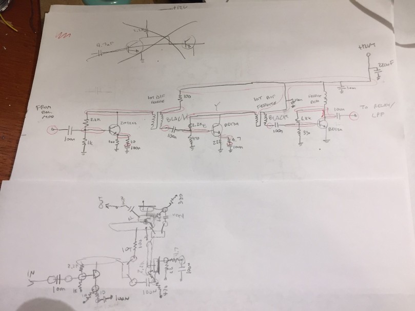
First on the bench is the continuation of my Beach 40 Transceiver project, that I’ve been working on since the Fall. I’ve been making steady progress recently on the penultimate stage, the RF amplifier, which will take the ~10dBm modulated voice signal from the balanced modulator and turn it into ~33dBm (2W) of RF output power to send to the LPF and out into the world. The amplifier is a three-stage design, with a 2n3904 buffer feeding a BD139 driver and another BD139 final.
Beach40 PA Schematic and Layout, in Graphite-O-Vision.
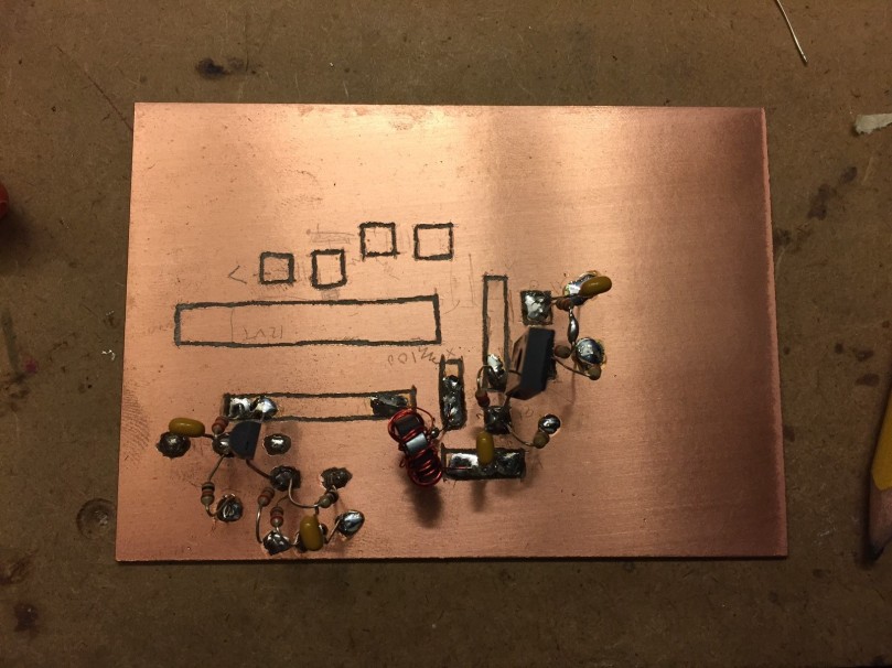
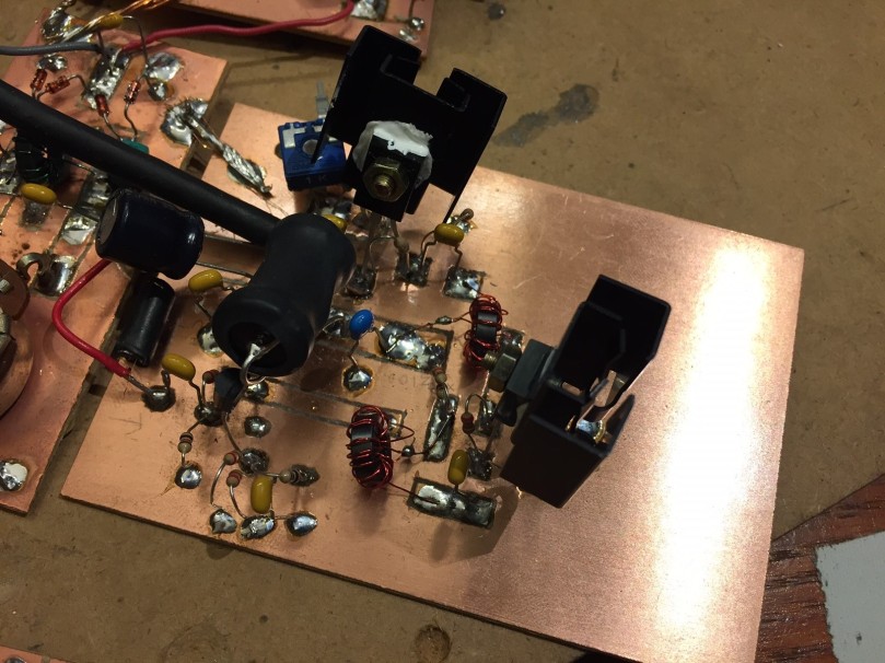
The module is assembled manhattan-style on single-sided copper glad, just like the rest of the project. The layout surrounds the +12V-on-transmit bus down the center of the PCB… more on that error later.
The Beach40 PA mid-assembly – you can see the +12VT buss running down the middle, and the buffer and driver stages starting to take shape.
The module assembly and testing went fairly smoothly – using a variable-voltage power supply, it’s easy to vary the output power of the amplifier, and to observe the changes in PA heating that this causes. You can see the two large screw-on heat sinks on the BD139’s in the following pictures, as well as the the large ferrite bead which feeds the Final. There’s also a chunky 100uF cap at the DC input to the board for additional decoupling.
The assembled Beach40 PA.
The problem I’m having now is the same one that plagued me way back in my assembly of the Virgin Receiver, my first first homebrew receiver: this amplifier would really love to be an oscillator. With the PA voltage set at 12V, any time the signal imput is sufficiently strong, the PA will fall hard into oscillation, and won’t stop until the PA voltage is brought way down or cut. I’ve been experimenting with emitter degeneration for the final BD139 (the original schematic has the emitter directly grounded). That’s helped, but not much. I’ve also changed the RF-carrying wires from hookup wire to coax, to mitigate feedback through other modules. Another help, but so far, the oscillation problem is still there. The next step will be to move the modules themselves around, to limit the amount that the high-power RF coming from the PA has to pass by earlier stages of the transmit chain (VFO, mic amp, balanced modulator) to try to eliminate feedback that way. Fingers crossed!
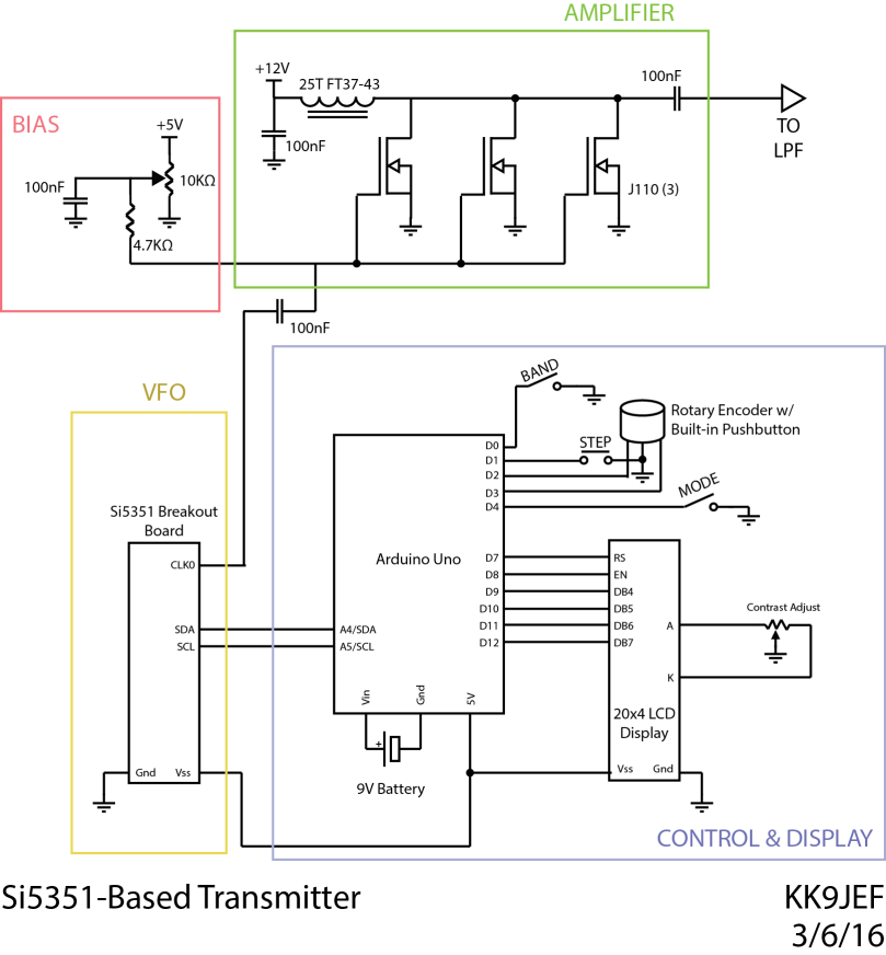
Next on the bench is a repackaging of an old project – my SI5351-based “VFO,” which for the better part of a year has been serving as my primary signal generator for experimental projects, spread out in all its Al-Fresco glory on a breadboard. With the amount of troubleshooting I’ve been going through on the Beach 40 project, I’ve decided to finally box up the SI5351, Arduino, and display into a proper project box, and make the thing a real SI5351-based Signal Generator. The schematic is essentially unchanged (minus the PA) since I used the project in my SI5351-based transmitter project, which is reproduced below:
To that end, I purchased an inexpensive nibbling tool and an expensive project box from the local Fry’s electronics, and have been working in the past couple weeks to marry the spread-out guts of the previous project with the clean lines of the enclosure. Biting out the large hole for the display 1/8″ at a time was time-consuming and strangely soothing.
At this point, the display and Arduino are connected, but I have yet to wire the two control buttons, rotary encoder, and Si5351 breakout board back into the Arduino. I also need a provision for getting the signal out the front of the darn thing, so I’m waiting on a shipment of SMA connectors and a jumper to go from the SI5351 breakout board to the front panel. So far, so good.
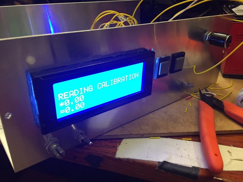
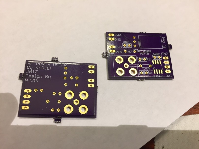
The last project on the bench is an RF power meter circuit, based on a circuit by W7ZOI from 2001. While the old scope-probe-across-a-50-ohm-load technique has proven very useful, I’ve found myself wanting a way to more reliably measure RF power at low levels, and to do it in a way that could be interfaced to a microcontroller or computer. To that end, I plan on using the W7ZOI circuit connected to an Arduino, much like Vu2ESE’s Sweeperino, to make digital power measurements.
I rolled a little PCB for this project from OSHPark, and since that service provides PCBs in multiples of 3, I figure I’ll connect one board to an analog meter (for that old-school feel), one to an independent Arduino (for digital measurements), and embed one inside the SigGen project, for marrying signal generator and power measurement at specific frequencies. This last project, I figure, will be especially useful for examining filter behavior at HF and piping the information to a PC for display an analysis.
So that’s what’s on the bench at the end of March 2017. All of these will hopefully merit full posts in future as the projects come to fruition, but for now, the is the smorgasbord that is my bench.
In a further example of the benefits of DX contests for those looking to rack up new countries, this weekend’s Russia DX Contest served up another bounty of new DXCC entities on CW.
All in all, I landed 11 new DXCC entities. Since part of the fun of contesting is imagining the operator at the other end of the ionosphere – doing the same thing you’re doing, furiously decoding CW in front of a radio, thousands of miles away – I’ve included the names of the ops below where I could find them:
Switzerland (HB9ON – Radiogroup in Piancamara 7, a profilic DXpedition team)
England (M2G – not a special event station, just a contest call of John in the UK)
Croatia (9A7V – Eugen)
Poland (SN8B – Bobowsi)
Germany (DA0AA – A radio club in Germany. “Emergency Radio Station Frank Cut Switzerland”, says Google Translate…. so that’s something)
European Russia (RU1A, a contest station out of St. Petersburg)
Northern Ireland (MI5I – Colin)
Serbia (YT3X – Miki)
Sweden (SH1DX – could not find)
Argentina (L6HKA – could not find)
Slovenia (S51J – Janez)
A bevy of new European countries worked during RDXC 2017. Argentina can come too.
I also connected with a second Alaska station, my first AK contact on 20m, which should help to cement that state for my WAS goal this year. (To be sure, KL7/VE7ACN has been tearing up the bands this week, since I heard him a week ago. But more contacts in the log never hurt.) As icing on the cake, I heard, but couldn’t contact, Arthur 4X2M in Israel . Still searching for that first elusive contact in Asia.
Unlike the ARRL DX contest, where contacts within the same country don’t count for anything, the Russia DX contest does award a (small) number of points for contacts in the same country. So I picked up a few stateside contacts on 40m later in the evening, just to add to the contact count and continue drilling my CW.
There’s a joke in radio circles about “contest propagation”, which is the notion that even when “the bands are dead,” they somehow “magically open up” when there’s a contest going on. Certainly, during major contests, when everyone who has one brings out their big amplifiers and aims their beams most precisely, contacts are more frequent.
But this weekend, I suspect that the ol’ ionosphere was actually on our side for a change – in the late afternoon, after I’d worked what there was to work on 20m CW and before 40m opened up, I dipped over onto 20M JT65. . After noodling around for about 20 minutes, I had landed both PD7RF (Frits in the Netherlands) and MC0CSO in Wales.
Two more DXCC in the log. That brings me up to 49 DXCC entities reached, with 30 confirmed.
And as a final sign of Sol’s grace upon the upper atmosphere, the following afternoon I heard (but could not reach) both Asiatic Russia (RA0CGY) and Japan (JM7OLW, JH1HRJ, JA1PSS, and 7K4GUR) on JT65.All are over 6000 miles away. They were way below the noise floor at -20 to -24 dB, about the limits of what JTDX will decode. But things look promising as the summer months move closer.
Stations heard on 20m JT65, afternoon of 3/19/17. What a spread! Image by PSKreporter.com
Just put Alaska in the log – KL7/VE7ACN was coming in about S7 to Chicago this evening, and I bagged him after about 10 minutes of chasing. To make it extra special, I he was working split on 7.001.5 UP, which makes this both (a) my first use of the Split feature of the FT-767 to work a station and (b) my first use of my Extra class privileges!
Per my New Year’s resolution, I only have 5 states left to work: Indiana, North Dakota, Nebraska, Nevada, and Utah. With 9 month’s left this year, I’m feeling confident about hitting all five before 2017’s end.
Yesterday, I went out to the Sterling IL Hamfest. It was quite a hike from my QTH in Chicago, but it turned out to be totally worth it: I finally upgraded to an Extra class license!
I’ve been casually studying for the Element 4 exam (extra class) for be past few months, with an eye toward upgrading at some point. But what really pushed me into action this weekend was a single Croatian station working the ARRL DX SSB contest, down in the part of 20m that I, as a general, wasn’t allowed to transmit on. He was at least 10-over-S9, just begging to be worked, but I couldn’t… so, a few more practice tests and a two hour drive later first thing Sunday morning, I had the Element 4 exam in hand. An hour after that, I had my Extra.
There were a few more finds at the fest – the club table had a big ole junk in of parts. Mostly miscellaneous circuit breakers and switches, but way down at he bottom were seven or eight multi-turn pots for $0.75 each. What a steal! I bought as many as I could pull out of the bin. I also pulled a few NP0 caps an a bag of 12V DPDT relays.
What a rush of a day it was. Looking forward to excercising my new frequency privileges this week.
Hear you on the air, wherever in the band you are!
I put a new DXCC entity in the log last week: Hungary
I ran across HG5F calling CQ TEST on morse code on 14.086 MHz on February 25th. This was smack in the middle of the UBA DX CW contest, which is actually a Belgian contest, but thankfully that awards points to non-Belgian countries making contacts with other non-Belgian countries. Admittedly, I wasn’t worth many points.
So, why did a Hungarian station come in at a solid 579 during the local afternoon on 20m, when he wanted to be talking to Belgium? There are two parts to unfolding that mystery. The first is John, HG5F’s, antenna; his QRZ page shows a large beam antenna (tribander?) in the foreground, on top of maybe a 30′-40′ tower. That would certainly have helped. (There’s also a small beam in the background of the picture, perhaps for 40m.)
HG5F’s antennas, from QRZ.com
The second and more interesting reason that HG5F was so audible has to do with geography. HG5F’s QRZ page lists his QTH (home station) as Jakabszállás, Hungary, a little Southwest of Budapest. If John was pointing his beam toward Belgium, (say toward Brussels in the center of the country,) his beam would have been pointed at roughly 300° ENE. If instead John had wanted to point his beam directly at me, he would have been aiming at ~310°. Put another way – by aiming his beam toward Belgium, John was also aiming toward the midwest United States.
These coincident transmission angles become clear when one looks at them with the proper map projection. Something like an azimuthal-equidistantmap, which displays all points as proportionally equidistant from a center point, is perfect for this task. Check out the following AE map centered on Budapest:
Notice that, from John’s perspective in Hungary, Belgium and the US Midwest line on almost the same Northeasterly line. Here’s the same illustration in a more familiar equirectangular map projection:
So, I was quite a bit of an overshot for John, but I’m always happy to make a transatlantic contact – and on CW no less! That makes 35 countries in the log so far, and with the ARRL SSB DX contest this weekend, I’m hoping to hear and work several more.
Though I’m very late to the ballgame in New Year’s resolutions, it being February and all, I do have one that settled on at the beginning of the year that I’m ready to commit to. 2017 is going to be the year that I get my Worked All States award.
Worked All States, or WAS, is a certificate handed out by the ARRL for those who have worked all 50 states in some form or another. I’ll be going specifically for WAS Mixed, which allows contacts of any type – phone, CW, or digital – to count, though there are individual awards for working all 50 states with each one of those modes as well.
So far, progress is promising. Given that I only got on HF last summer, I’m already within striking distance of my goal. Only 7 states have eluded me so far: Alaska and Hawaii (no surprise), Nevada and Utah (far to the West with small populations of hams), North Dakota and Nebraska (see comment about the sparsity of hams), and Indiana (my signals must be skipping right over them). I’ve actually knocked three states off the list just recently: I picked up Idaho, Delaware, and Wyoming during the two January North American QSO parties.
Beyond that, there are 10 more states I’ve contacted but don’t have official confirmation for: Wyoming, Iowa, Missouri, Arkansas, Louisiana, Michigan, Mississippi, West Virginia, Massachusetts, and Rhode Island. The other 33 states are in the log and confirmed.
Here’s the current status of things, laid out in visual form (Grey is unworked, blue is worked and unconfirmed, green is confirmed):
Here’s to 8 more states in 10 more months. Hear you on the air!
Stop Press: Between the time I wrote this post and the time it was scheduled to be posted, I made contact with Hawaii! Specifically with KH6LC on 21.0295 MHz during the ARRL DX CW contest. We’ll see if it gets confirmed, but that means only 6 states left to find. I also received confirmation for Rhode Island in an unrelated JT65 QSO. The map has been updated with these changes.


