
With an eye toward getting my rudimentary Si5351-based transmitter on the air, I’ve started putting together a number of low pass filters to knock down some of the nasty harmonics that come with using a clock chip as a frequency generator.
The filters are all based on the designs given by W3NQN in the GQRP technical pages from 2015. (This is another point at which I’m taking design inspiration from the QRP-Labs QRSS beacon.) The paper lists both the target values for each of the toroids and capacitors for a 7-pole low pass filter for each band, as well as the required number of turns for each toroid and an appropriate toroid to use. For this project, since my target frequencies range from about 7 MHz to 14 MHz, I’m using all T37-6 toroids from KitsAndParts.com. The basic design of each filter is the same:
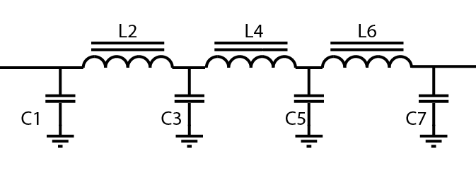
| Band | C1, C7 | C3, C5 | L2, L6 | L4 |
|---|---|---|---|---|
| 20m | 180pF | 390pF | .773uH | .904uH |
| 30m | 270pF | 560pF | 1.090uH | 1.257uH |
| 40m | 270pF | 680pF | 1.380uH | 1.698uH |
Unfortunately, I don’t have exactly the specified capacitors in my kit, so here’s my approximation to these values. (Note that the number of turns is different at 40m than W3NQN recommends, to more closely match the specified inductance). All inductors are wound on a T37-6:
| Band | C1, C7 | C3, C5 | L2, L6 (turns) | L4 (turns) |
|---|---|---|---|---|
| 20m | 1000+220 (series) = 180pF | 1000 + 690 (series) = 408 pF | 16T = .77uH | 17T = 0.87uH |
| 30m | 220+47 = 267pF | 220+220+100 = 540pF | 19T = 1.08uH | 20T = 1.20uH |
| 40m | 220+47= 267pF | 470+220=690pF | 21T = 1.32 | 24T = 1.73uH |
Some quick simulations in LT Spice confirms that these little adjustments don’t have an enormous effect on the filter’s behavior. On 40M, for example, it has the effect of moving the cutoff frequency down maybe 100 KHz:


With this filter on my little homebrew transmitter, I finally made my first (official) WSPR contact… but that’s a story for another post.
Hear you on the air!
73
